High-Fidelity Electromagnetic Simulation of Indirect Lightning Effects on Military Aircraft Wiring Systems
Discover how Ansys EMC Plus enables engineers to simulate indirect lightning effects on military aircraft cables — from Zone 1 strike injection to shielding validation — without costly full-scale physical tests.
ME
Mohd Esa
Jan 16, 20266 min read
Military aircraft are struck by lightning on average 10.5 times per 10,000 flying hours in Europe. While aircraft are designed with extensive lightning strike protection to safely conduct high currents and electromagnetic fields, full-scale physical lightning testing is costly and can delay design corrections — and scaled models often fail to replicate full-size responses accurately.
Virtual testing through advanced electromagnetic and multiphysics simulation enables engineers to study lightning strike effects on aircraft structure and cables efficiently, optimising protection strategies without extensive physical prototypes. Ansys EMC Plus can comprehensively evaluate electromagnetic behaviour on complex platforms by analysing radiated coupling to cables, coupling through shields, and EMI crosstalk between adjacent harnesses — all within a single integrated workflow.
Section 01Lightning and its Effects on Aircraft
Lightning is a natural atmospheric discharge phenomenon characterised by large transient currents. During a strike, current can rise extremely rapidly — on the order of 10–20 kA/µs. Lightning activity is especially frequent within the troposphere (0–12 km altitude), which coincides with the primary flight altitudes of commercial and military aircraft.
Approximately 90% of cloud-to-ground (CG) lightning strikes are downward negative lightning, transferring negative charge from the cloud to the ground. The conductive skin of an aircraft acts as a Faraday cage, offering a low-resistance path for electrons and shielding occupants from stray electrical charges.
Lightning effects on aircraft are divided into two primary categories:
Direct effects — Physical damage at the lightning attachment point (punctures, burns).
Indirect effects — Electromagnetic coupling of the lightning current with onboard wiring, producing transient disturbances that can interfere with or degrade electronic and electrical components.
Additional hazards include fuel system ignition risk, crew incapacitation, engine failure from control system malfunctions, and thermal damage to materials and critical systems.
Section 02Stages in Aircraft Lightning Attachment Simulation
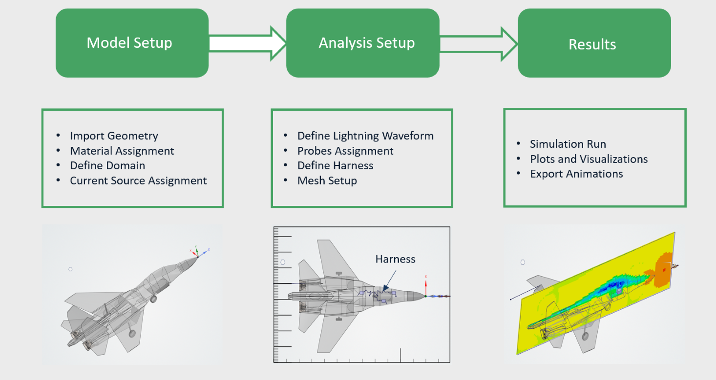
Figure 1 · Lightning Attachment Simulation Stages on a Military Aircraft
All three stages of aircraft lightning simulation can be completed within a single interface in Ansys EMC Plus:
Pre-processing — Assigning material properties and cable harness location, defining current source, mesh settings, and probes.
EM Simulation — The FDTD solver calculates fields around the aircraft using voxel mesh. The Multi-Conductor Transmission Line (MTL) solver handles complex cable configurations.
Post-processing — Simulation results are transformed into a format suitable for direct comparison with measured data or further analysis.
Section 03Current Waveshape and Lightning Attachment
Lightning waveforms in aircraft simulations typically follow a double-exponential shape. Ansys EMC Plus supports standard versions of these waveforms to model indirect lightning effects. This study employs a double-exponential waveform with a 218 kA peak current and an approximate rise time of 6.4 µs — representing one of the most severe worst-case scenarios for assessing lightning-induced transients in aircraft wiring.
Aircraft certification under SAE ARP5412 uses these waveforms for Zone 1 and Zone 2A areas, where attachment points experience full current intensity. In accordance with SAE ARP5414, the aircraft nose is designated as Zone 1 — the primary attachment zone. For this study, the standardised current waveform is injected at the aircraft nose.
218kA
peak current — worst-case waveform
6.4µs
rise time — double-exponential
Zone 1
primary lightning attachment (nose)
Section 04Cable Layout & Shielding Terminations
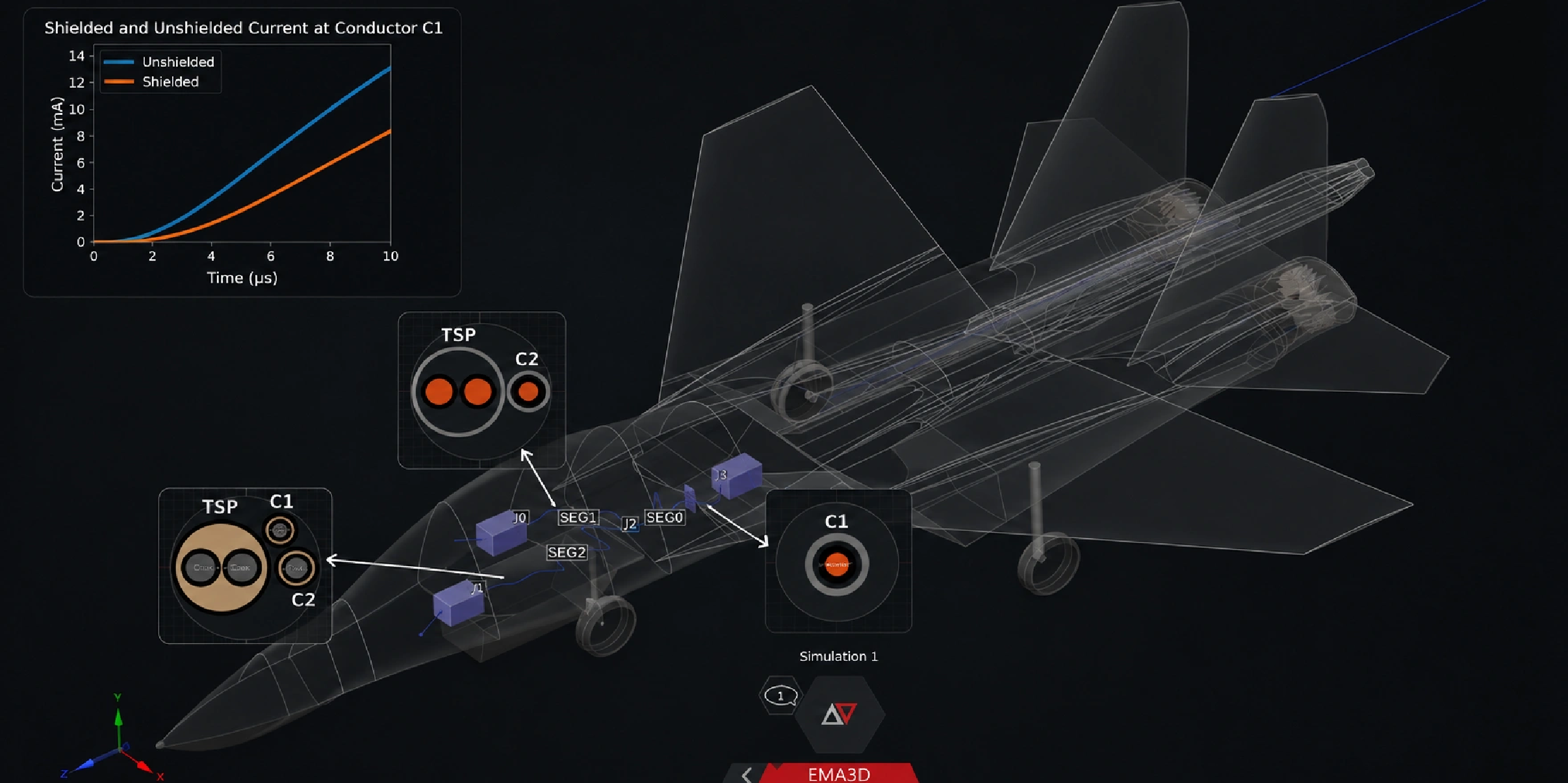
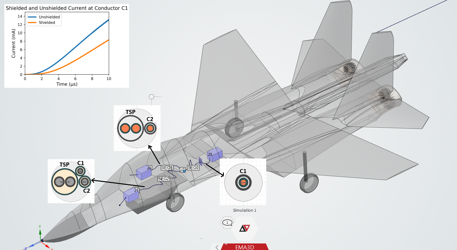
Figure 2 · Aircraft Wiring Harness Configuration and Resulting Conductor C1 Current for Shielded and Unshielded Cases
Ansys EMC Plus uses a hybrid FDTD-MTL approach for cable and end terminations. A 16 AWG twisted shielded pair (TSP) cable, along with two 24 AWG bare conductors (C1 and C2), is defined and assigned within the harness. Initially, C2 has a shield while C1 remains unshielded.
The Cable Inspect Cross Section feature enables visualisation and verification of multi-layer cable bundle geometries along their routed paths. A current probe is placed on conductor C1 to measure the current induced by indirect lightning effects:
With C1 unshielded — higher induced current, greater vulnerability to transients.
With C1 shielded — significantly reduced induced current, demonstrating the effectiveness of shielding.
Section 05Lightning Probability Simulation Capability
EMC Plus delivers advanced lightning probability simulation through seamless integration with Ansys STK. This goes beyond traditional lightning attachment simulation and aircraft zoning analysis by evaluating lightning strike probability along the complete aircraft mission profile.
The automated Lightning Probability workflow enables users to run a full simulation with a single click — computing lightning strike probability along an aircraft's trajectory for specific missions and providing actionable insights to support risk mitigation and mission planning.
Conclusion
Ansys EMC Plus offers a robust solution for evaluating lightning-induced indirect effects on aircraft cables. By simulating Zone 1 strikes with cable routing and shielding tests, it enables accurate assessment and mitigation of induced currents. The Tool allows visualization of electromagnetic field and electric current propagation, validation of harness designs, reducing reliance on costly full-scale tests. Compliant with standards, EMC Plus supports the development of safer, lightning-resilient aircraft while saving time and cost in the design process.