Element design · array synthesis · installed performance · automotive integration
Full-wave antenna simulation covering element design, impedance matching, installed antenna performance on vehicle and device platforms, phased array synthesis, radome design, and automotive multi-band integration — from concept to validated antenna system.
What We Deliver
Antenna performance in the real product environment differs substantially from free-space element measurements. Our antenna simulation team models the complete system — from element geometry optimisation and impedance matching through to installed performance on the full vehicle, device, or platform — capturing all ground plane, body-loading, and coupling effects that determine real-world system performance.
We cover element design and optimisation, impedance matching, installed antenna performance, phased array synthesis, radome and FSS design, and automotive multi-band antenna integration across commercial, automotive, and aerospace applications.
Key Problems We Solve
6 Analysis Areas
Select a capability to explore the methodology, deliverables, and tools in detail.
ANALYSIS TYPE / 01
radiation pattern · bandwidth · efficiency
Designing and optimising antenna elements for target frequency bands, radiation patterns, bandwidth, and efficiency — from initial concept geometry through parametric optimisation to final validated antenna element design ready for integration.
Key Aspects
Developing antenna element geometries — patch, monopole, dipole, slot, PIFA, helix — and parametrically optimising dimensions for target resonant frequency, bandwidth, and efficiency.
Computing 3D radiation patterns, gain, HPBW, front-to-back ratio, and polarisation characteristics across the target frequency band and evaluating pattern compliance with system link requirements.
Evaluating radiation efficiency, total efficiency including mismatch losses, and surface current distribution to identify dominant loss mechanisms and guide material and geometry improvements.
Applying techniques including parasitic elements, meandering, slot loading, and substrate optimisation to extend antenna bandwidth while maintaining target gain and pattern characteristics.
ANALYSIS TYPE / 02
S11 · VSWR · matching network design
Designing impedance matching networks to achieve maximum power transfer from the feed system to the antenna element — optimising S11, VSWR, and return loss over the target operating band for single-band, multi-band, and wideband antenna systems.
Key Aspects
Characterising antenna input impedance as a function of frequency using full-wave simulation, generating broadband impedance data for matching network synthesis and system integration.
Designing L-network, T-network, PI-network, and transmission line matching topologies to transform antenna impedance to system impedance (50 Ω) across the target frequency band.
Developing matching networks that simultaneously cover multiple operating bands — 4G/5G, GNSS, Wi-Fi, Bluetooth — without requiring switched matching, maintaining compact PCB footprint.
Evaluating tunable matching networks using RF switches and varactors for adaptive antenna impedance control in reconfigurable radio systems and handset designs with body-loading effects.
ANALYSIS TYPE / 03
vehicle · platform · body-loading effects
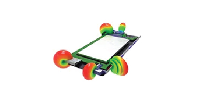
Simulating antenna performance when installed on the full vehicle, aircraft, ship, or device platform — capturing body-loading effects, ground plane resonances, and mutual coupling that alter the element-level antenna characteristics in real operating environments.
Key Aspects
Meshing and solving the complete vehicle or platform geometry with the antenna integrated in its installation location, capturing the full electromagnetic effect of the surrounding structure on antenna performance.
Quantifying how proximity to metallic structures, composite panels, and absorbing materials detunes the antenna resonance, degrades efficiency, and distorts the radiation pattern relative to free-space performance.
Evaluating multiple antenna mounting positions and orientations on the platform to identify the location that best satisfies coverage, efficiency, and integration constraint requirements simultaneously.
Analysing how PCB ground plane size, shape, and surrounding metal influence resonant frequency, radiation efficiency, and pattern for compact antenna systems in handheld and IoT devices.
ANALYSIS TYPE / 04
phased array · beamsteering · sidelobe control
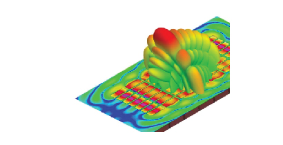
Designing antenna arrays with controlled beam patterns — synthesising element spacing, excitation amplitude, and phase distributions for pencil beams, shaped beams, null steering, and adaptive beamforming in radar, 5G mmWave, and satellite communication applications.
Key Aspects
Synthesising element excitation coefficients for target beam patterns using Dolph-Chebyshev, Taylor, and custom weighting — balancing mainlobe gain, sidelobe level, and null depth requirements.
Computing mutual coupling between array elements and correcting excitation coefficients for coupling effects — ensuring the embedded element patterns and active impedances match array synthesis assumptions.
Evaluating beam squint, gain roll-off, and impedance mismatch as the array beam is steered off broadside — defining the usable scan volume and identifying performance degradation mechanisms at wide scan angles.
Designing element spacing and array geometry to suppress grating lobes across the full operating band and scan volume, ensuring no unintended high-gain radiation directions within the application field of regard.
ANALYSIS TYPE / 05
transmission loss · FSS passband · structural integration
Designing radomes and frequency selective surfaces for antenna systems requiring aerodynamic enclosures, environmental protection, or frequency-selective filtering — optimising wall construction, FSS geometry, and structural integration to minimise antenna performance degradation.
Key Aspects
Computing electromagnetic transmission through radome wall constructions including monolithic, A-sandwich, and B-sandwich designs — evaluating insertion loss, beam deflection, and pattern distortion over scan angle and frequency.
Designing FSS geometries — patch, ring, cross, and Jerusalem cross elements — for required passband and stopband frequencies, with controlled bandwidth and out-of-band rejection tailored to the host antenna system.
Evaluating radome and FSS transmission characteristics for oblique incidence angles, both TE and TM polarisations, ensuring performance is maintained across the full operational field of regard.
Integrating RF performance requirements with structural load-bearing and environmental sealing requirements — balancing wall thickness, material selection, and FSS geometry for combined structural and electromagnetic compliance.
ANALYSIS TYPE / 06
V2X · GNSS · cellular · shark-fin · MIMO
Designing and validating antenna systems for automotive applications — covering GNSS, 4G/5G cellular, V2X, short-range radar, and shark-fin integration — with full-vehicle simulation to achieve multi-band coverage and regulatory compliance.
Key Aspects
Designing integrated antenna systems covering LTE/5G (700 MHz–6 GHz), GNSS (L1/L2/L5), V2X (5.9 GHz), and Wi-Fi/Bluetooth bands within constrained automotive mounting locations and aesthetic requirements.
Evaluating MIMO antenna system performance including envelope correlation coefficient, mean effective gain, total active reflection coefficient, and diversity gain to assess multi-antenna system capacity.
Simulating full-vehicle models to evaluate how body panels, roof geometry, window coatings, and nearby metallic structures affect pattern coverage, efficiency, and band separation for each antenna port.
Validating antenna system performance against ETSI, FCC, and automotive OEM specifications for gain, coverage, efficiency, and EMC compliance — generating pre-certification documentation for antenna homologation.
Talk to our Centre of Excellence team about element design, phased array synthesis, installed performance analysis, or automotive multi-band antenna integration.