From field to compliance — precision EM engineering across every domain
Comprehensive electromagnetic engineering services spanning antenna design, signal integrity, EMI/EMC compliance, RF circuits, and power electronics — enabling reliable, high-performance electronic systems across aerospace, automotive, and industrial applications.
What We Deliver
Our electromagnetics team covers the full spectrum of EM simulation — from antenna array design and signal integrity at multi-GHz data rates to motor efficiency mapping and busbar thermal analysis. We work with the most capable EM solvers to deliver actionable results at every frequency and every scale.
Whether you are pre-compliance testing a PCB against CISPR 25 or optimising a permanent magnet motor for EV traction, our engineers identify the right simulation approach and deliver verified results on schedule.
Key Problems We Solve
10 Analysis Types
Select an analysis type to explore the methodology, deliverables, and tools in detail.
ANALYSIS TYPE / 01
radiation pattern · gain · impedance matching
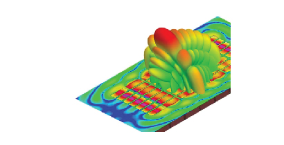
Antenna simulation covers the design, tuning, and validation of antenna elements and arrays — computing radiation patterns, gain, impedance matching, polarisation, and efficiency across operating frequency bands for automotive, aerospace, and consumer electronics applications.
Key Aspects
Solving Maxwell's equations using FEM or FDTD methods to accurately model the radiation and near-field behaviour of antenna structures at any frequency band.
Optimising feed network and matching circuits to achieve target return loss and bandwidth — extracting S-parameters for direct comparison with VNA measurements.
Simulating the antenna in its installed environment — including vehicle body, composite radome, or complex housing — to predict the real-world gain pattern and coupling.
Designing and optimising phased array antenna layouts, element spacing, and excitation weights to achieve target beam shape, sidelobe level, and beam steering range.
ANALYSIS TYPE / 02
transmission loss · angle dependence · polarisation
Radome and frequency selective surface (FSS) simulation evaluates transmission loss, cross-polarisation, and angle-of-incidence effects — enabling optimised enclosure designs that protect antennas without degrading RF performance.
Key Aspects
Computing the insertion loss and phase error introduced by the radome wall over the full scan angle range — ensuring the system gain budget is met at all operating conditions.
Designing periodic FSS resonant elements — patches, crosses, Jerusalem crosses, or complementary shapes — to achieve bandpass or bandstop responses at target frequencies.
Evaluating the cross-polar discrimination degradation introduced by the radome — critical for dual-polarisation and MIMO antenna systems.
Assessing the shift in FSS resonance and transmission loss increase caused by wet or iced radome surfaces — informing de-icing requirements.
ANALYSIS TYPE / 03
high-speed interconnects · crosstalk · eye diagram
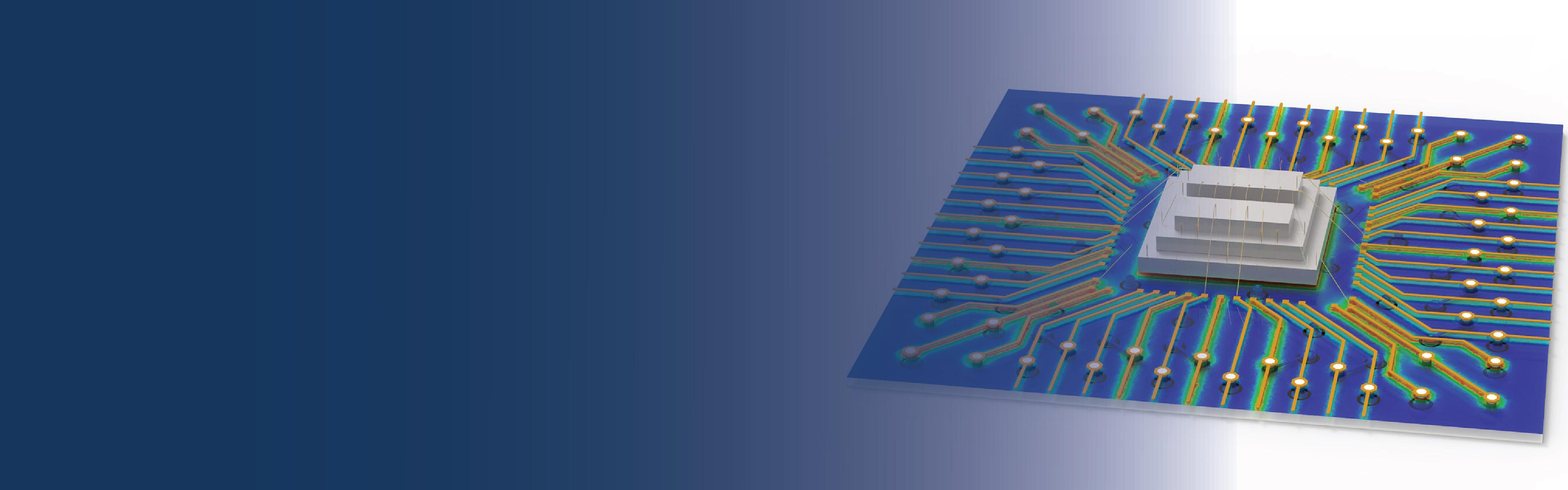
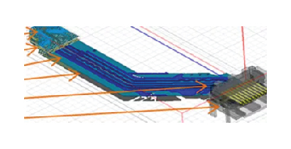
Signal integrity analysis addresses reflections, crosstalk, impedance discontinuities, and electromagnetic emissions in high-speed digital interconnects — ensuring reliable data transmission in PCBs, packages, and system-level designs at multi-GHz data rates.
Key Aspects
Identifying vias, connectors, bends, and reference plane gaps that create impedance mismatches and generate reflections — recommending geometry changes to smooth the transmission line profile.
Computing near-end (NEXT) and far-end (FEXT) crosstalk between adjacent signal traces and differential pairs — guiding routing rules and spacing requirements.
Simulating complete channel performance at the bit rate of interest — generating eye diagrams, BER estimates, and jitter decomposition for compliance margin evaluation.
Evaluating decoupling capacitor placement, plane resonance, and target impedance compliance to ensure stable power delivery to high-speed ICs under switching transients.
ANALYSIS TYPE / 04
pre-compliance · emission · susceptibility
EMI/EMC simulation identifies electromagnetic emission sources, coupling paths, and susceptibility issues in electronic systems — enabling pre-compliance verification and design fixes before costly physical chamber testing.
Key Aspects
Computing far-field radiated emissions from PCBs, cables, and enclosures — comparing against CISPR 25, FCC Part 15, or EN 55032 limits to identify non-compliant frequency ranges.
Analysing conducted noise on power and signal lines — evaluating EMI filter effectiveness and grounding strategy for compliance with LV 124, CISPR 25, and similar standards.
Simulating the system's response to external electromagnetic fields — evaluating immunity to BCI, bulk current injection, RF immunity, and ESD events.
Computing the attenuation provided by metal enclosures, shielded cables, and EMI gaskets — identifying apertures and cable exits that reduce shielding performance.
ANALYSIS TYPE / 05
filters · couplers · resonators · S-parameters
RF passive circuit simulation covers the electromagnetic analysis of filters, couplers, power dividers, resonators, and transmission line structures — extracting S-parameters, insertion loss, and spurious response characteristics for microwave and mmWave applications.
Key Aspects
Designing bandpass, bandstop, and low-pass filters in microstrip, stripline, or waveguide — optimising element values and layout for target passband ripple, return loss, and stopband rejection.
Computing coupling and isolation of directional couplers, power dividers, and hybrids — validating amplitude and phase balance across the operational bandwidth.
Accurately predicting the loaded and unloaded Q-factor of cavity, dielectric, and planar resonators — critical for oscillator phase noise and filter insertion loss.
Identifying spurious resonances and harmonics that degrade filter out-of-band rejection — guiding layout modifications to push spurs outside the operating band.
ANALYSIS TYPE / 06
torque · efficiency · loss · thermal coupling
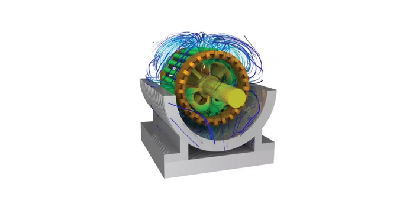
Electric motor and generator simulation computes torque, efficiency, losses, flux distribution, and thermal behaviour in AC induction motors, permanent magnet machines, switched reluctance drives, and generators across the full operating envelope.
Key Aspects
Computing torque-speed characteristics, efficiency maps, and power factor across the full operating range — identifying peak efficiency regions and de-rating under field weakening.
Decomposing total machine losses into iron core loss, copper winding loss, eddy current loss, and magnet loss — identifying the dominant contributors for each operating point.
Evaluating permanent magnet operating point under fault current, temperature extremes, and field-weakening — predicting irreversible demagnetisation risk and margin.
Iteratively coupling electromagnetic loss maps with thermal CFD to predict winding and magnet temperatures under sustained operating cycles — informing cooling system design.
ANALYSIS TYPE / 07
force-stroke · transient response · inductance
Actuator and solenoid simulation evaluates force–stroke characteristics, transient pull-in and release response, inductance, and power consumption — supporting the design of solenoid valves, linear actuators, relays, and voice-coil mechanisms.
Key Aspects
Computing the electromagnetic force as a function of armature position at rated current — mapping the complete force-stroke profile for actuator sizing and spring preload design.
Simulating the coupled electromagnetic-mechanical dynamics to predict actuation time, bounce, and response to drive voltage waveform — optimising coil design for speed and energy.
Extracting position-dependent inductance for circuit modelling and predicting back-EMF during motion — inputs for drive electronics design and control loop tuning.
Evaluating how coil resistance increase at elevated temperature affects pull-in force and response time — establishing the temperature-derated operating envelope.
ANALYSIS TYPE / 08
core loss · leakage inductance · insulation stress
Transformer simulation addresses core loss, leakage inductance, winding proximity effects, insulation stress, and thermal hotspots — enabling optimised designs for power distribution, isolation, and high-frequency switching transformers.
Key Aspects
Computing hysteresis and eddy current losses in magnetic cores using material B-H curves and Steinmetz loss models — predicting core operating point and saturation margin.
Accurately extracting the leakage inductance from the 3D electromagnetic field distribution — a key parameter for switching converter voltage regulation and ZVS design.
Modelling skin and proximity effect in high-frequency transformer windings — predicting the effective AC resistance and its impact on winding loss at switching frequency harmonics.
Computing electric field distribution in the insulation system under rated, surge, and impulse voltage — identifying stress concentrations that risk partial discharge or breakdown.
ANALYSIS TYPE / 09
current distribution · Joule heating · EMI · mechanical stress
Busbar simulation analyses current density distribution, Joule heating, inductance, and mechanical stress under rated and fault conditions — ensuring reliable power distribution in EV battery systems, switchgear, and power electronics.
Key Aspects
Predicting the non-uniform current distribution in complex busbar geometries and identifying thermal hotspots under normal and peak current conditions.
Computing the frequency-dependent loop inductance of the busbar arrangement — critical for limiting voltage overshoot during IGBT and SiC MOSFET switching.
Coupling electromagnetic losses to thermal conduction to predict steady-state and transient temperature rise — verifying compliance with insulation temperature limits.
Simulating the extreme currents and resulting forces during short-circuit events — verifying structural integrity of the busbar assembly under fault conditions.
ANALYSIS TYPE / 10
inductive · capacitive · Hall-effect · sensitivity
Sensor simulation models the electromagnetic operating principle, sensitivity, linearity, and cross-sensitivity of inductive, capacitive, Hall-effect, and eddy-current sensors — supporting miniaturisation and performance optimisation for automotive and industrial applications.
Key Aspects
Computing the sensor output signal (inductance change, capacitance change, or flux density) as a function of the measurand — generating the transfer function and sensitivity coefficient.
Evaluating sensor output linearity across the full measurement range — identifying saturation, non-linearity, and hysteresis that limits resolution and calibration stability.
Assessing sensitivity to out-of-axis displacements, temperature, adjacent magnetic materials, and external magnetic fields — informing shielding and mounting design requirements.
Evaluating how reducing sensor dimensions impacts sensitivity, linearity, and signal-to-noise ratio — enabling informed decisions about minimum viable sensor size.
Connect with our EM simulation team to discuss the right approach for your application.