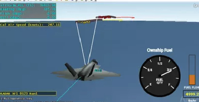
From hazard identification to ASIL compliance — end to end.
Functional safety analysis is a systematic approach used to identify, assess, and mitigate risks associated with the functional behaviour of safety-critical systems. Key aspects include hazard identification, risk assessment, and implementation of safety measures in accordance with ISO 26262, ARP 4754, and IEC 61508.
What We Deliver
Our functional safety engineering team supports the complete safety lifecycle — from initial item definition and HARA through to FMEDA, FTA, and independent assessment. We work to applicable standards across automotive, aerospace, and industrial domains, delivering the analysis artefacts and traceability evidence required for certification and design release.
Whether you need a full safety case from the ground up or targeted support for a specific analysis type, our team integrates with your development process and tooling to deliver compliance-ready outputs on schedule.
Standards Coverage
10 Analysis Types
Select an analysis type to explore the methodology, key aspects, and applicable standards in detail.
ANALYSIS TYPE / 01
standards compliance · lifecycle support
We provide end-to-end support for compliance with the three major functional safety standards — ISO 26262 for road vehicles, ARP 4754 for aerospace, and IEC 61508 for industrial systems. This includes process tailoring, work product creation, and independent assessment across the full development lifecycle.
Key Aspects
Determining which standard applies — and at what integrity level — based on the system type, operational context, and regulatory territory.
Defining the safety activities, roles, responsibilities, and schedule across all phases — from concept through decommissioning — as required by the applicable standard.
Creating the full set of required safety work products: safety plans, arguments, reports, checklists, and assessment packages aligned to the relevant standard clause structure.
Providing third-party assessment to confirm that the safety case is complete, consistent, and meets the standard's requirements before submission or design release.
ANALYSIS TYPE / 02
system boundary · function allocation
Item definition establishes the system boundary, operational design domain, functions, and interfaces of the safety-relevant item. It is the foundational input for HARA and all subsequent safety planning — and must be complete before risk assessment can begin.
Key Aspects
Establishing what is inside and outside the item — including hardware, software, sensors, actuators, and human interaction points.
Listing all functions the item performs, including primary safety-relevant functions and secondary operational functions.
Documenting all electrical, mechanical, and logical interfaces between the item and its environment, including assumed system-level constraints.
Defining the environmental conditions, operational modes, and use cases within which the item is required to function safely.
ANALYSIS TYPE / 03
hazard identification · risk rating · ASIL assignment
HARA (Hazard Analysis and Risk Assessment) systematically identifies hazardous events resulting from system malfunctions, assesses their severity and controllability, and assigns ASIL ratings — providing the safety goals that drive all downstream safety requirements.
Key Aspects
Combining system functions with operational situations and failure modes to enumerate all credible hazardous situations that could arise from malfunctioning behaviour.
Assessing each hazardous situation against the severity of injury (S0–S3) and the ability of a driver or third party to control the situation (C0–C3).
Estimating the frequency and duration of exposure to each operational situation (E0–E4) — a key parameter in the ASIL classification.
Combining S, E, and C ratings to determine the ASIL (QM, A, B, C, D) for each hazardous event and formulating the corresponding safety goals.
ANALYSIS TYPE / 04
top-level goals · functional requirements · technical allocation
Safety goals are decomposed into functional safety requirements and then into technical safety requirements, allocated to system elements and verified through model-based safety analysis — ensuring full traceability from hazard to design implementation.
Key Aspects
Translating safety goals into functional safety requirements at the system level — defining what the system must do (and not do) to maintain safe state.
Decomposing functional safety requirements into technical requirements allocated to hardware and software elements, with defined safety mechanisms for each.
Splitting ASIL requirements between two independent channels to reduce the individual ASIL target for each — enabling more cost-effective hardware implementation.
Maintaining a complete, auditable trace from every safety goal through functional and technical requirements to design elements and verification results.
ANALYSIS TYPE / 05
failure rate · PMHF · quantitative targets
Reliability analysis quantifies the probability of hardware failure for electrical and electronic systems using failure rate databases such as IEC TR 62380, MIL-HDBK-217, and SN29500 — supporting PMHF and random hardware failure metric compliance under ISO 26262.
Key Aspects
Selecting appropriate failure rate data sources (IEC TR 62380, MIL-HDBK-217, SN29500, or manufacturer data) for each component in the design.
Computing the Probabilistic Metric for random Hardware Failures (PMHF) for ASIL B, C, and D functions to confirm compliance with the ISO 26262 quantitative targets.
Classifying all failure modes as safe or dangerous, detected or undetected, to calculate the SFF and verify that it meets the minimum threshold for the hardware safety integrity level.
Assessing how temperature, vibration, humidity, and operating hours affect the failure rate — and adjusting the PMHF calculation accordingly for the specific application environment.
ANALYSIS TYPE / 06
failure mode identification · effect analysis · criticality ranking
FMEA and FMECA identify potential failure modes of system elements, assess their effects on system function and safety, and prioritise corrective actions through RPN or criticality ranking — covering design FMEA, process FMEA, and system FMEA in accordance with relevant standards.
Key Aspects
Analysing each component's potential failure modes and their effects on the function, subsystem, and vehicle — identifying design changes that eliminate or mitigate risk.
Evaluating interactions between subsystems and identifying failure modes that only emerge at the system integration level — including interface failures and parameter mismatches.
Extending FMEA with quantitative criticality ranking — combining failure probability and severity to prioritise corrective actions in safety-critical systems.
Analysing manufacturing and assembly process steps for failure modes that could introduce latent defects — essential for ASIL C/D hardware production compliance.
ANALYSIS TYPE / 07
top-down deductive · failure logic · probability of violation
Fault Tree Analysis (FTA) models the logical combination of hardware failures, software faults, and external events that could lead to a system-level hazardous event — providing a structured basis for quantitative probability of failure calculations and safety argument support.
Key Aspects
Building a top-down logic model from the top-level hazardous event through AND/OR gates to the root failure causes at component or function level.
Identifying all minimal combinations of basic events that are sufficient to cause the top event — revealing single-point failures and critical dependency paths.
Computing the probability of the top event from component failure rates and the Boolean logic of the fault tree — verifying compliance with ASIL-level targets.
Calculating Birnbaum, Fussell-Vesely, and Criticality importance measures to rank basic events by their contribution to system-level failure probability.
ANALYSIS TYPE / 08
diagnostic coverage · SPFM · LFM · PMHF verification
FMEDA extends FMEA with quantitative failure rate data and diagnostic coverage analysis to verify that the safety mechanism architecture achieves the required SPFM, LFM, and PMHF targets specified by ISO 26262 for each hardware element.
Key Aspects
Classifying each failure mode as safe or dangerous, and as detected or undetected by the safety mechanism — the foundation for all subsequent metric calculations.
Computing the DC for each safety mechanism by comparing its ability to detect dangerous failure modes against the total dangerous failure rate of the monitored element.
Calculating the Safe Failure Fraction and Latent Fault Metric for each hardware element and verifying compliance with the minimum thresholds required for ASIL B, C, and D.
Accumulating the residual risk contribution of each undetected dangerous failure mode to the system-level PMHF — confirming the overall target is met.
ANALYSIS TYPE / 09
system reliability · availability · redundancy architecture
Reliability Block Diagram (RBD) analysis models the logical dependencies between system components to evaluate overall system reliability, availability, and safety integrity — particularly useful for redundant, parallel, and standby system architectures.
Key Aspects
Modelling component interdependencies in series (all must work), parallel (any can work), and standby (backup activates on failure) configurations to compute system-level metrics.
Computing the probability that the system performs its required function over the specified mission time — accounting for component failure rates and repair times.
Calculating steady-state and time-dependent system availability — critical for safety systems with maintenance intervals and proof-test requirements.
Comparing alternative redundancy architectures (1oo2, 2oo3, hot standby) against reliability and cost targets to select the optimal safety architecture.
ANALYSIS TYPE / 10
common cause · common mode · independent channel verification
Dependent Failure Analysis (DFA) identifies common cause failures (CCF) and common mode failures (CMF) that could simultaneously affect independent or redundant channels — a mandatory activity for ASIL C and ASIL D systems under ISO 26262.
Key Aspects
Identifying shared resources — power supplies, ground planes, temperature environments, software platforms — that could cause concurrent failure in supposedly independent channels.
Evaluating design similarities between redundant channels that could produce identical failure responses to the same input stimulus — defeating diversity.
Verifying that spatial, thermal, electrical, and software separation between redundant channels is sufficient to prevent correlation of failures.
Specifying design changes — diversity, isolation, physical separation, or monitoring — to reduce CCF and CMF contributions to an acceptable level.
Connect with our safety engineering team to define the right analysis approach, timeline, and tooling for your project.