What Is a Battery Management System? Guide for Automotive Applications
Read the CADFEM guide to smart BMS functions, automotive thermal management, centralized vs. modular architectures, and Ansys simulation
Read Article →
Walk through the complete workflow for weld fatigue analysis of a vehicle subframe — from geometry preparation and shell seam weld setup in Ansys Mechanical to fatigue life prediction in Ansys Design Life.
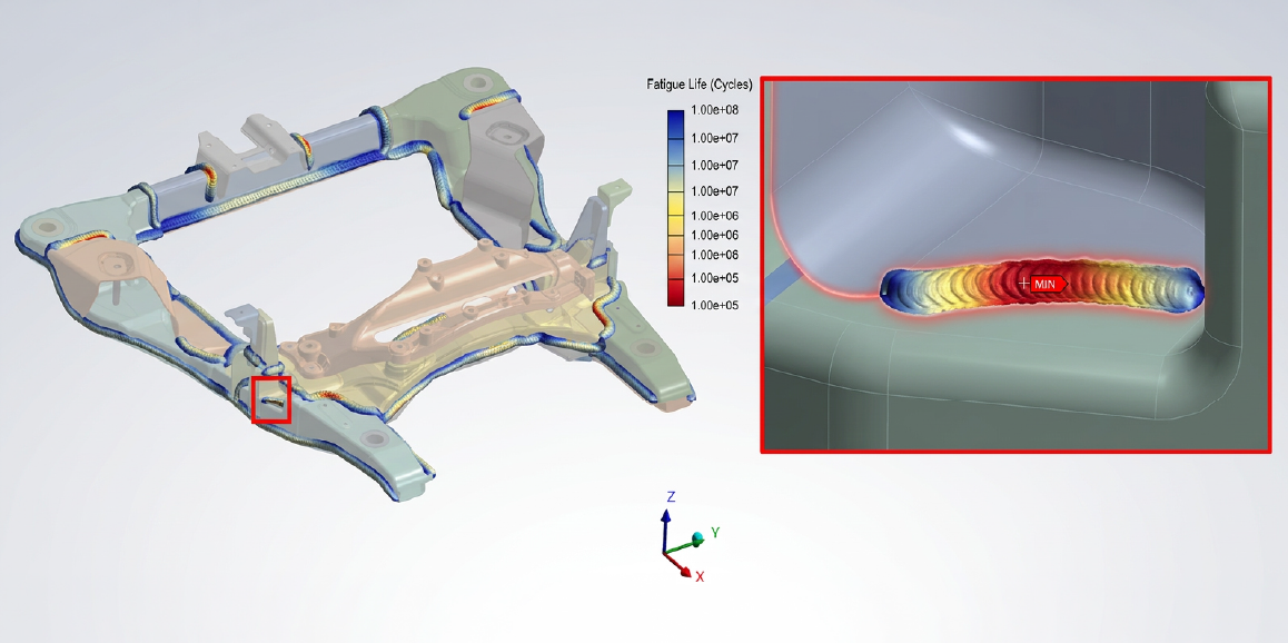
Vehicle structures are constantly subjected to repeated loading from road conditions, braking, acceleration, and vibration. Among all structural components, the vehicle subframe plays a crucial role in supporting suspension systems and transferring loads throughout the chassis. Because of these repeated load cycles, fatigue failure becomes a major design concern, particularly in welded joints.
Welds are often the weakest points in a structure when it comes to fatigue performance. During welding, residual tensile stresses are introduced, which can accelerate crack initiation. In addition, weld material typically exhibits lower fatigue resistance than the base metal, and the geometric features of welds create stress concentrations that make them ideal locations for fatigue cracks to start.
To address these challenges, engineers rely on advanced durability analysis tools such as Ansys Design Life. This tool enables engineers to predict fatigue life accurately and identify critical weld locations early in the design stage, helping ensure safer and more reliable vehicle structures.
In this blog, we will walk through the fatigue evaluation of welded joints in a vehicle subframe, demonstrating how the simulation workflow is carried out.
Before running a fatigue simulation, it is important to select the appropriate weld fatigue methodology. Ansys Design Life provides multiple approaches depending on the type of weld and the modelling strategy used in the finite element model:
| Analysis Type | Application |
|---|---|
| Shell Seam Weld | For shell elements (thin plate welds) |
| Solid Seam Weld | For solid elements (thick plate welds) |
| Spot Weld | For localized welds |
| Stress Life (S–N) | Based on stress cycles (high cycle fatigue) |
| Strain Life (E–N) | Based on strain cycles (low cycle fatigue) |
This method is typically used when structures are modelled with shell elements, which are common for thin sheet metal components. The approach is particularly suitable for sheets with thicknesses around 1–3 mm, such as automotive body panels.
One major advantage of this method is that it does not require highly refined meshes or detailed weld geometry. Instead, fatigue damage is evaluated at the weld toe and weld root, considering both membrane and bending stresses acting on the structure.
When the structure is modelled with solid elements, particularly for thicker plates, the solid seam weld method becomes more appropriate.
In this method, stress linearization techniques are used to recover structural stresses within the weld region. This approach is relatively mesh-insensitive, making it reliable even when the mesh density varies. It also enables fatigue evaluation at several critical regions, including the weld toe, weld root, and weld throat.
Automotive assemblies frequently contain spot welds, especially in thin sheet structures. The spot weld fatigue method evaluates durability based on cross-sectional forces and moments acting around the weld.
Fatigue calculations are performed at multiple angular increments around the weld edge, and the worst-case fatigue life is reported. In addition, Python scripting capabilities allow engineers to extend the methodology to simulate other joining techniques such as rivets or bolts.
Fatigue analysis can also be categorized based on the fatigue regime:
These methods support several advanced fatigue considerations, including mean stress effects, temperature influence, stress gradients, and surface finish corrections.
Now that the available analysis methods are understood, let's explore how the weld fatigue analysis of a vehicle subframe is performed using Ansys tools. In this case study, the Shell Seam Weld method is used because the subframe components are sheet metal structures modelled using shell elements.
The workflow begins with geometry preparation in Ansys SpaceClaim or Ansys Discovery. Here, the surfaces of sheet metal components are extracted, and weld lines are defined as curves representing the location of the welded joints.
These weld curves are then modelled as beam elements, which allows the weld geometry to be represented without explicitly modelling the weld bead.
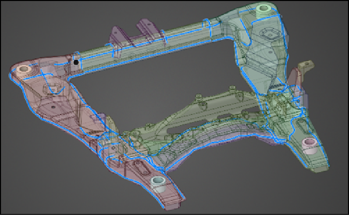
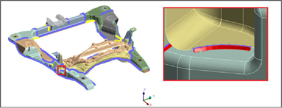
Next, the prepared model is imported into Ansys Mechanical, where the welds are generated using the Weld Mesh feature.
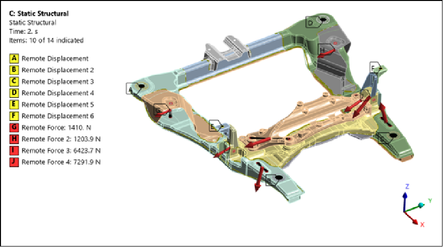
A structural analysis is performed to determine the stress and strain distribution within the subframe under loading conditions. This step is critical because the fatigue simulation relies on these stress results as input data.
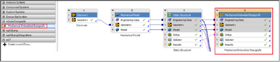
Once the structural analysis is completed, the solution is connected directly to an embedded Design Life system within the Ansys Workbench environment. This integration allows stress results from the structural analysis to be automatically transferred to the fatigue module without additional preprocessing.
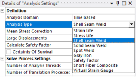
Within the fatigue analysis setup, the Shell Seam Weld method is selected.
The next step is to define the loading history using the Load Mapper tool in Design Life. Several load types are available depending on the nature of the input data:
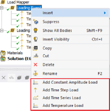
The different types of the load are described below.
| Load Type | Description | Typical Use Case |
|---|---|---|
| Constant Amplitude | A simple cyclic load with fixed amplitude and frequency. | Quick fatigue checks, baseline studies, or when loading is repetitive and uniform. |
| Time Step | Load data defined at discrete time steps. Each step corresponds to a specific load magnitude. | Useful when simulation results are exported as time histories with evenly spaced steps. |
| Time Series | Continuous load history over time, capturing variations in amplitude and frequency. | Real-world measured data (strain gauge, road load data, vibration signals). Best for durability studies. |
| Temperature Load | Accounts for thermal effects on fatigue life. Temperature is applied as a varying or constant input. | When fatigue behaviour is strongly influenced by thermal cycling (e.g. exhaust systems, engine parts). |
In this example, a time-step loading event is used. The structural analysis results are applied at three discrete time points (1, 2, and 3), and the loading cycle is repeated 2000 times to simulate repeated operational conditions.
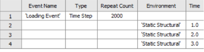
After defining the loading events, the fatigue simulation is launched in Ansys Design Life. The software processes the stress histories and applies fatigue damage models to evaluate crack initiation and fatigue life at each weld location.
The results are then displayed using contour plots, which highlight regions of high fatigue damage and identify the most critical weld locations within the subframe. These insights allow engineers to quickly determine whether design modifications are required to improve durability.
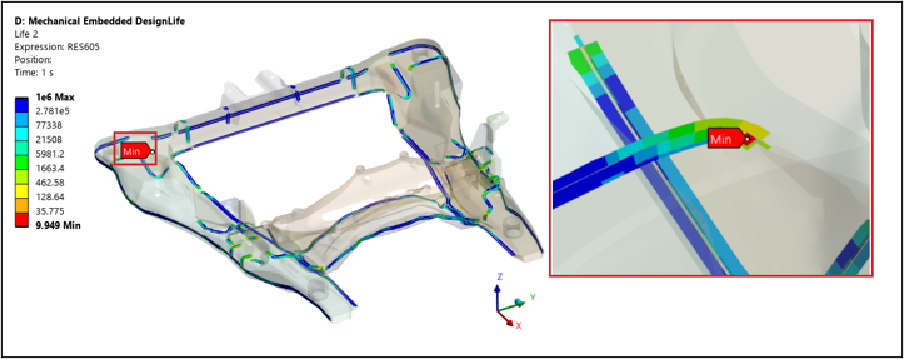
Fatigue failure in welded structures is a critical concern in the automotive industry, particularly for components such as vehicle subframes that experience repeated dynamic loading throughout their service life. By combining the geometry preparation capabilities of Ansys Space Claim / Ansys Discovery, the structural analysis capabilities of Ansys Mechanical, and the advanced fatigue evaluation tools available in Ansys Design Life, engineers can perform comprehensive weld durability assessments. This integrated workflow not only helps identify potential fatigue failures early in the design process but also enables engineers to optimize weld locations, improve structural reliability, and reduce the risk of costly failures in the field. Ultimately, adopting such advanced simulation-driven design approaches allows manufacturers to build stronger, safer, and more durable vehicles while accelerating product development cycles.
As an authorized Ansys channel partner, CADFEM supports customers throughout their simulation journey by providing expert technical guidance, customized workflows, advanced training, and hands-on implementation support. From model setup and parameter calibration to validation and optimization, CADFEM helps organizations fully leverage Ansys wear simulation capabilities to achieve reliable, high-quality engineering solutions. Together, Ansys Mechanical and CADFEM enable engineers to make informed design decisions, improve product durability, and accelerate innovation through simulation-driven development.
 Multi Physics
Read the CADFEM guide to smart BMS functions, automotive thermal management, centralized vs. modular architectures, and Ansys simulation
Read Article → Structures
Di tengah pesatnya perkembangan teknologi rekayasa, adopsi CAE di Indonesia menjadi kunci utama dalam meningkatkan efisiensi dan produktivitas berbagai sektor industri.
Read Article → Electronics
Learn how to use Ansys HFSS SBR+ for 77 GHz automotive radar simulation, evaluating radome effects, antenna performance, radiation patterns, and installation.
Read Article →Connect with CADFEM experts for advanced simulation, automation, and engineering solutions tailored to your industry.