What Is a Battery Management System? Guide for Automotive Applications
Read the CADFEM guide to smart BMS functions, automotive thermal management, centralized vs. modular architectures, and Ansys simulation
Read Article →
Master the Archard wear model in Ansys Mechanical — from APDL setup and CONTA element configuration to contact pressure post-processing and interpreting progressive wear results.
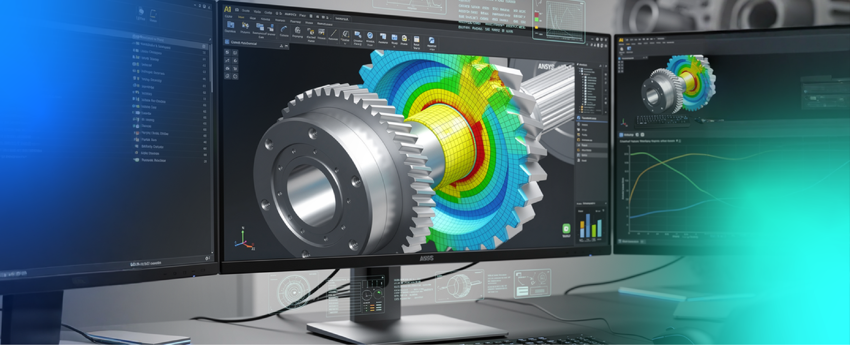
Wear is the progressive loss of material from a surface caused by repeated mechanical contact. In engineering components such as bearings, gears, fasteners, and seals, wear plays a critical role in determining long-term reliability and performance. If left unaccounted for, excessive wear can lead to dimensional changes, efficiency loss, and even premature failure.
Ansys Mechanical provides powerful capabilities to simulate wear behaviour using established empirical models, with the Archard wear model being the most widely used approach.
In this blog, we will discuss how wear is represented in Ansys, how to implement the Archard model in practical simulations, the use of APDL commands for advanced control, post-processing techniques for evaluating wear results, and key meshing guidelines for obtaining accurate and reliable predictions.
In finite element analysis (FEA), wear is modelled by shifting nodes on contact surfaces to represent material loss. After each update, the model re-establishes equilibrium and contact conditions. Since the contact geometry continuously evolves, wear simulations are inherently nonlinear and require iterative solution procedures.
Ansys Mechanical represents wear at the continuum scale using empirical relationships that connect contact pressure, relative sliding motion, and material resistance to surface degradation.
Wear modelling in Ansys is supported only for specific contact element types:
To activate wear behavior, a wear material model must be assigned to the contact elements using the TB,WEAR material definition in Mechanical APDL, since Ansys Mechanical does not allow wear to be defined directly through the GUI.
Ansys provides two primary methods for simulating wear:
In this article, we focus mainly on the native Archard wear model and its implementation in the Ansys Mechanical GUI.
The Archard wear model is the most widely used empirical approach for predicting material loss due to sliding contact. It estimates the wear rate based on the combined effects of contact pressure, relative motion, and material hardness. In Ansys Mechanical, the generalized form of the Archard wear equation is expressed as:
ẇ = K · Pm · vn / H
Where:
The exponents m and n allow the wear model to capture nonlinear dependencies on contact pressure and sliding velocity. These values are typically obtained through experimental calibration by fitting wear test data (such as pin-on-disc or block-on-ring tests) under varying loads and sliding speeds. In many standard applications, both values are set to 1, reducing the formulation to the classical Archard law.
By default, the calculated wear displacement is applied in the direction opposite to the contact normal, representing material removal perpendicular to the contact surface. However, Ansys also allows users to modify the wear direction using directional input parameters. This flexibility is useful for modelling applications where wear follows a preferred sliding direction or is influenced by complex surface kinematics.
Wear modelling in Ansys Mechanical is activated by defining a wear material model using the TB,WEAR command. Together with TBDATA, it allows users to specify the constants that control wear behaviour on contact surfaces. This APDL-based setup is useful when advanced control over wear parameters is required.
Below are the basic command parameters for enabling the Archard wear model:
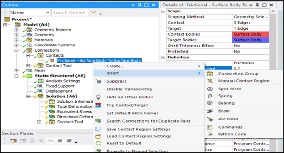
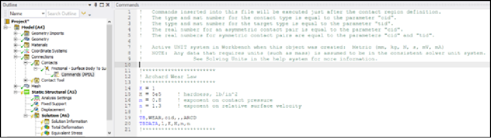
Notes:
The following post-processing approaches can be used to evaluate wear behaviour and its effect on contact conditions:
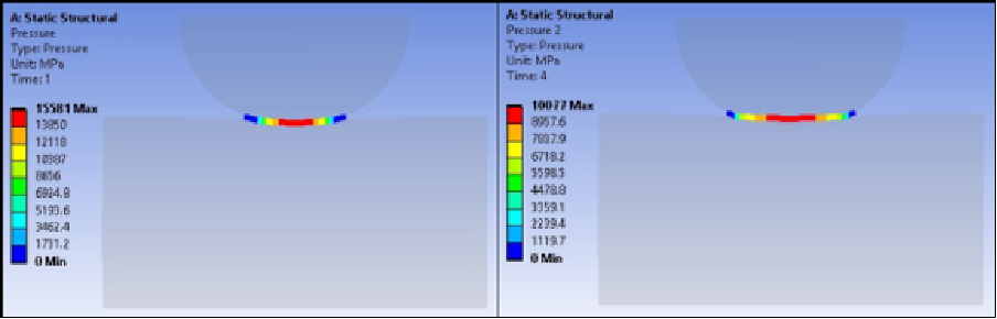
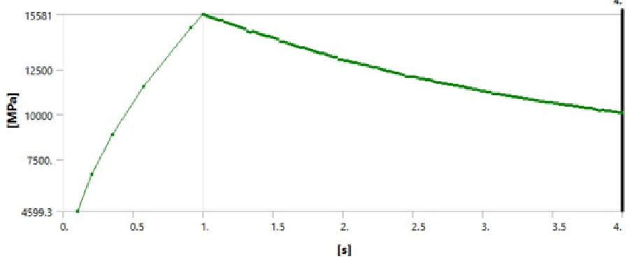
It can be observed that beyond a certain point, the contact pressure starts to decrease — indicating progressive surface wear. As wear progresses, the contact geometry becomes more conformal, leading to a reduction in local contact pressure compared to the initial geometry.
Wear plays a critical role in determining the long-term performance and reliability of mechanical components. With its robust contact modelling capabilities, built-in Archard wear formulation, advanced APDL customization, and powerful post-processing tools, ansys Mechanical provides a comprehensive platform for accurately investigating wear behaviour under realistic operating conditions. Engineers can efficiently evaluate wear progression, predict material loss, and optimize designs before physical testing, leading to reduced development time and cost.
As an authorized Ansys channel partner, CADFEM supports customers throughout their simulation journey by providing expert technical guidance, customized workflows, advanced training, and hands-on implementation support. From model setup and parameter calibration to validation and optimization, CADFEM helps organizations fully leverage Ansys wear simulation capabilities to achieve reliable, high-quality engineering solutions. CADFEM enable engineers with the help of Ansys Mechanical to make informed design decisions, improve product durability, and accelerate innovation through simulation-driven development.
 Multi Physics
Read the CADFEM guide to smart BMS functions, automotive thermal management, centralized vs. modular architectures, and Ansys simulation
Read Article → Structures
Di tengah pesatnya perkembangan teknologi rekayasa, adopsi CAE di Indonesia menjadi kunci utama dalam meningkatkan efisiensi dan produktivitas berbagai sektor industri.
Read Article → Electronics
Learn how to use Ansys HFSS SBR+ for 77 GHz automotive radar simulation, evaluating radome effects, antenna performance, radiation patterns, and installation.
Read Article →Connect with CADFEM experts for advanced simulation, automation, and engineering solutions tailored to your industry.