Understanding Terrain Fidelity in Mission Analysis with Ansys STK
When engineers think about mission analysis, attention naturally goes to the vehicle, trajectory, sensor, communications system, or target.
SS
Sanjeev S
Oct 16, 20268 min read
Introduction — The Ground Is Not Flat
When engineers think about mission analysis, attention naturally goes to the vehicle, trajectory, sensor, communications system, or target. But there is another part of the mission environment that is often taken for granted: the ground itself.
In a real mission, an aircraft does not fly over a perfectly smooth mathematical surface. A sensor does not observe a target through an empty geometric space. A communication link between two ground-based assets does not necessarily have an unobstructed path between them.
Mountains, valleys, slopes, ridges, and elevation changes can all become part of the mission geometry..
This raises an important question:
If the mission remains the same, can changing the way we represent the terrain change the analysis result ?
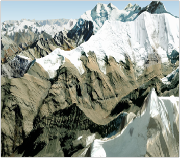
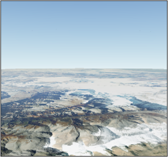
Side-by-side comparison with and without terrain in Ansys STK
The answer depends on the mission and the level of terrain fidelity required.
In Ansys STK, terrain can be incorporated into mission analysis rather than being used only to improve the appearance of the 3D scene. STK documentation describes terrain-based analysis for applications including line-of-sight restrictions, sensor footprint intersection, object altitude, terrain masks, and other mission calculations.
This makes terrain more than a background layer. For the right mission, the digital representation of the ground can become an engineering input.
Section 01Why Does Terrain Matter in Mission Analysis?
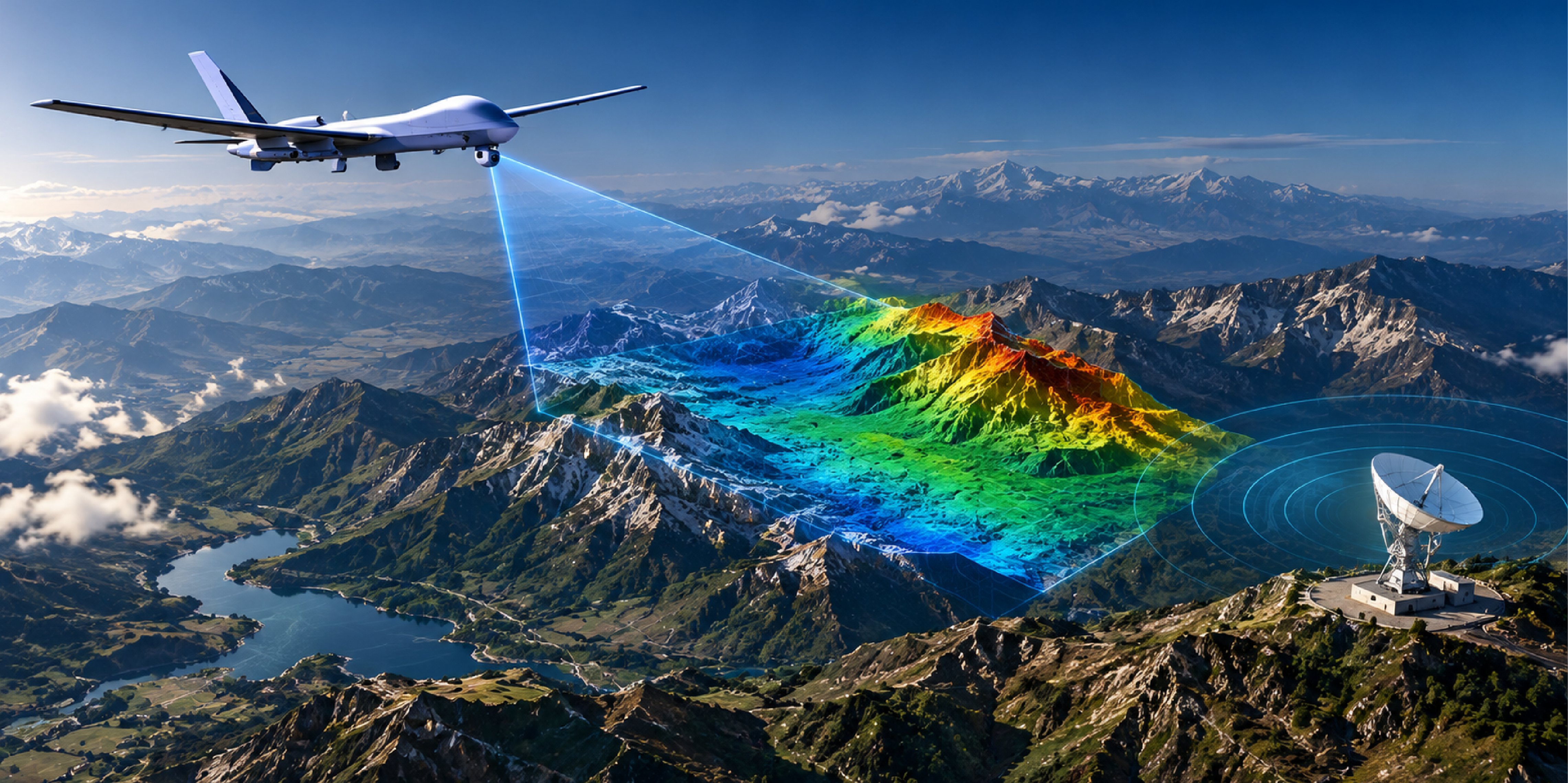
Consider a simple scenario: a UAV is flying over uneven terrain while its onboard sensor is observing a ground target.
From a purely geometric perspective, the sensor may have a direct path toward the target. But that does not necessarily mean the target is visible.
A ridge between the UAV and the target may obstruct the line of sight.
The same concept applies to other mission-analysis problems:
Sensor missions: Terrain can obstruct the line of sight between a sensor and its target.
Communications: Terrain can affect whether a ground-to-ground or ground-to-air path is unobstructed.
UAV operations: Terrain elevation can influence the relationship between vehicle altitude and the surrounding environment.
Ground-station analysis: Local terrain can affect visibility and masking around a site.
Coverage and access: Terrain can constrain when an asset can observe or communicate with another object.
STK provides specific terrain-based analysis capabilities for these situations. Its documentation describes a Terrain Mask constraint that can restrict access when terrain intersects the line of sight. STK also distinguishes this higher-fidelity terrain-based approach from its simpler line-of-sight ground model.
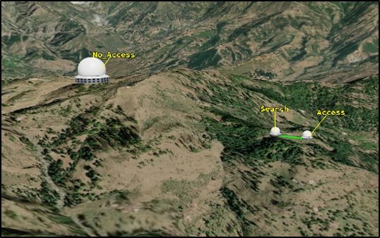
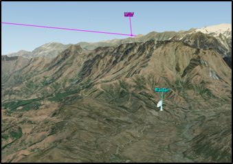
Terrain obstruction affecting line-of-sight access in STK
A mission analysis can produce a technically correct result for the ground model being used. The engineering question is whether that ground model represents the environment well enough for the decision being made.
That leads to the next question:
How much terrain fidelity does a mission need?
Section 02Understanding Terrain Fidelity
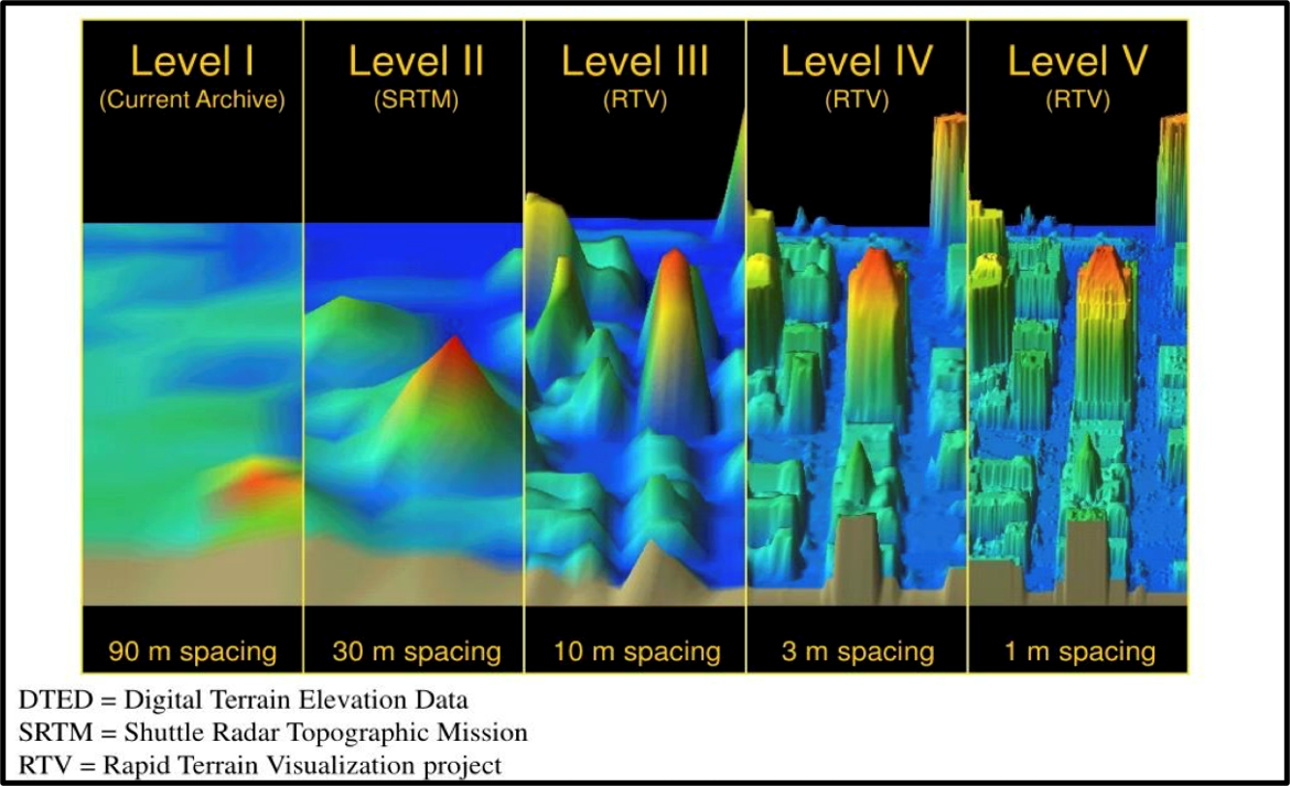
Terrain fidelity describes how closely the digital terrain model matches the environment's actual shape and elevation.
A broad regional analysis may not require the same level of terrain detail as a mission that depends on seeing a target behind a mountain ridge.
Notional Difference in DTED Resolution
For example, consider two hypothetical analyses:
Mission A — Regional mission planning
An analyst wants to understand the general location and movement of assets across a large geographic region. In this case, a broad terrain representation may be adequate for the intended analysis.
Mission B — Sensor visibility
An analyst wants to determine whether a UAV-mounted sensor can maintain visibility of a specific ground target in mountainous terrain. Here, local elevation changes can become much more important because relatively small terrain features may influence the line of sight.
The important point is therefore not simply:
“More terrain detail is always better.”
Instead, the engineering question should be:
“What level of terrain fidelity is appropriate for the question I am trying to answer?”
Ansys STK supports terrain data for more detailed modelling and analysis, including terrain-based line-of-sight restrictions and terrain-aware sensor analysis.
This makes terrain fidelity an engineering consideration rather than merely a visualisation preference.
In the sections that follow, we will look at how terrain can be represented in STK and then use a UAV and sensor scenario to examine how the representation of the ground can influence mission analysis.
Once terrain is recognised as an engineering input, the next question is how to represent it within a mission-analysis environment.
Ansys STK provides several ways to incorporate terrain into a scenario, from streamed terrain services to local datasets and detailed 3D Tiles. The right approach depends on the mission, geographic area, available data, and required fidelity.
Terrain from a terrain server
For many Earth-based scenarios, STK can stream terrain from a terrain server. By default, STK can connect to the AGI Terrain Server, allowing terrain data to be used for visualisation and analytical operations. The terrain server can also be configured according to the requirements of a particular scenario.
This approach is useful when analysts need terrain coverage over a large area without manually preparing terrain files for every region. It can support analyses where terrain elevation influences calculations such as line-of-sight and terrain masking. Valid Terrain Formats
Local or external terrain data
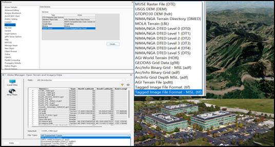
STK also supports locally available terrain datasets. External elevation data can be imported into a scenario and used for analysis, provided it is converted or supplied in a format supported by STK. Supported terrain sources include formats such as STK terrain files, USGS DEM, DTED, TIFF, and other elevation datasets.
This option becomes particularly useful when a mission requires a specific terrain dataset or when analysts need greater control over the terrain used in the simulation.
External terrain data and supported terrain formats in STK
3D Tiles and detailed terrain Representation
Modern mission environments can also contain much more detailed three-dimensional geometry. STK supports 3D Tilesets, which can represent terrain, photogrammetry, buildings, and other large-scale geographic datasets. Importantly, 3D Tiles are not limited to visual presentation: STK can use suitable 3D Tiles geometry computationally for analysis, including determining obstructions caused by terrain and stationary objects. Read more about 3d tiles capabilities
STK also provides tools for converting elevation datasets into 3D Tiles. This makes it possible to transform source elevation data into a tiled representation suitable for efficient visualisation and analysis.
The Important Distinction: Visualisation vs. Analysis
One important point is that seeing terrain in a 3D window does not automatically mean that the terrain is being used in every analysis calculation.
STK distinguishes between terrain used for visualisation and terrain enabled for analytical operations. For example, the Terrain properties allow terrain-server data to be enabled for analysis, while local terrain sources can also be added for analytical use.
This distinction is important because a realistic-looking 3D scene can give the impression that the mission is being evaluated against the visible terrain, while the actual analysis may depend on a different terrain source or configuration.
Therefore, when setting up a mission, the question should not simply be:
“Does the terrain look realistic?”
It should be:
“Is the terrain representation being used by the analysis appropriate for the engineering question?”
This becomes especially important for missions involving sensors, low-altitude aircraft, communications, or operations in mountainous and highly variable terrain.
The next section demonstrates this idea using a simple UAV, sensor, target, and terrain scenario.
Section 04Demonstration: UAV, Sensor and Terrain
To understand the practical effect of terrain fidelity, consider a simple mission scenario involving three elements: a UAV, an onboard sensor, and a ground target.
The objective is deliberately straightforward. The UAV follows a defined flight path while its sensor attempts to observe a target located on the ground. The surrounding terrain is included as part of the mission environment.
At first glance, this may appear to be a simple visibility problem. However, the terrain between the UAV and the target can introduce an important geometric constraint.
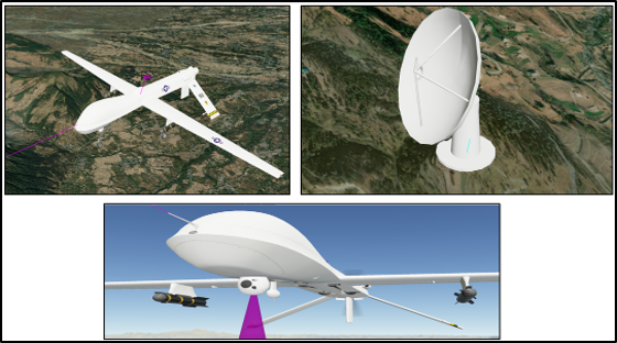
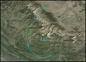
UAV and onboard sensor configuration for the terrain analysis.
Establishing the Mission Scenario
The demonstration can be constructed in Ansys STK using:
UAV: representing the airborne platform.
Sensor: attached to the UAV and directed toward the ground.
Ground target: representing the object the sensor is attempting to observe.
Terrain: representing the physical environment between the UAV and target..
Access or visibility analysis: used to determine when the sensor has an unobstructed view of the target.
The scenario is intentionally kept simple. The UAV trajectory, sensor characteristics and target location remain fixed throughout the experiment.
The terrain representation is the variable that will be changed.
This is important because it allows the effect of terrain fidelity to be examined without simultaneously changing the rest of the mission.
UAV and terrain-mask configuration shown in STK 3D and 2D views.
Establishing a Baseline
The first step is to establish a baseline using a selected terrain dataset.
The UAV is placed along its planned flight path, while the ground target is positioned in an area where surrounding terrain can potentially influence the sensor’s line of sight.
The sensor is configured to observe the target, and the resulting access or visibility intervals are recorded.
At this stage, the objective is not to determine whether one terrain dataset is better than another.
Instead, the purpose is to establish a reference case:
For this mission geometry, what does STK predict when this terrain representation is used?
The baseline provides the reference against which the next analysis can be compared.
This creates a controlled comparison between two terrain models describing the same geographic environment at different levels of detail.
The resulting visibility or access behaviour can then be compared to determine whether the terrain representation itself changes the mission-analysis result.
This is the key idea behind the demonstration:
Same mission. Same assets. Same geometry. Different terrain representation.
If the resulting analysis changes, the difference is no longer simply a matter of how realistic the 3D scene looks. It demonstrates that the representation of the ground can influence the mission analysis itself.
The next section examines exactly what can change when terrain fidelity changes—and whether those changes are significant enough to matter for engineering decisions.
Section 05What Changes When Terrain Fidelity Changes?
The UAV, sensor and target scenario established in the previous section provides a simple way to examine the effect of terrain fidelity directly within Ansys STK.
The mission geometry remains unchanged: the UAV follows the same trajectory, the sensor retains the same configuration, and the target remains at the same location. The terrain representation is the only variable being changed.
This allows STK to be used not only to visualise the difference between terrain datasets, but also to examine whether that difference affects the resulting mission analysis.
Comparing the STK Analysis
A coarse terrain representation may smooth or omit smaller elevation features, while a higher-fidelity representation can capture details such as local ridges, valleys and slopes. Within STK, these differences can become relevant to terrain-dependent analysis.
For the UAV scenario, the primary comparison is sensor-to-target line of sight and access. A terrain feature represented in one dataset but not another may change whether the sensor has an unobstructed view of the target at a particular point along the UAV’s trajectory.
The same principle can be applied to other STK analyses where terrain influences the geometry, including terrain masking and communication paths.
However, the presence of a higher-resolution terrain dataset does not automatically mean that the mission result will change significantly. The effect depends on the terrain itself, the platform altitude, the geometry between the assets and the type of analysis being performed.
What Should Be Measured?
Rather than comparing the terrain only by how it looks in the 3D window, the STK analysis can be compared using measurable outputs such as:
Sensor-to-target line-of-sight status
Access start and stop times
Total access duration
Aircraft-to-terrain altitude relationship
Visibility changes along the UAV trajectory
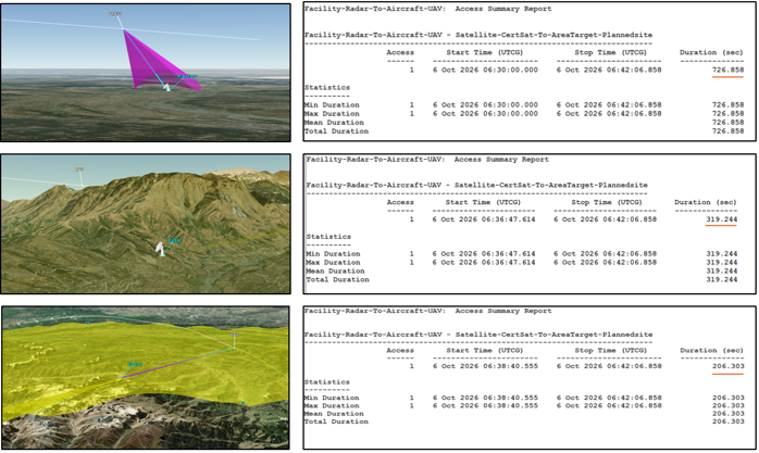
STK access analysis with no terrain, AGI Terrain Server, and external PDTT terrain
The results demonstrate that terrain representation can directly affect the calculated access interval. With no terrain enabled, access is available for 726.858 seconds. When the AGI Terrain Server is used, the calculated access reduces to 319.244 seconds. Using the external PDTT terrain further reduces the access duration.
The difference demonstrates that terrain fidelity is not only a visual consideration; it can directly influence the outcome of an STK mission analysis.
This is an important distinction. A terrain dataset may provide considerably more detail visually, but if that additional information does not change the STK analysis relevant to the mission, its engineering value may be limited for that application.
From Terrain Detail to Mission Decision
This leads to a practical way of thinking about terrain fidelity in STK:
The right terrain is not necessarily the most detailed; it is the terrain representation that is detailed enough for the analysis being performed. For a low-altitude UAV operating near mountainous terrain, local elevation features may be critical to sensor visibility. For a broader regional analysis, the same level of detail may provide little additional value.
The role of STK is therefore not simply to display increasingly detailed terrain, but to allow engineers to incorporate terrain into mission analysis and determine whether its level of fidelity matters to the decision being made.
The next section extends this idea beyond the UAV demonstration to other mission-analysis applications where terrain can become an important part of the STK environment.
Section 06Beyond UAVs: Where Terrain Can Matter
Terrain exerts a significant influence beyond the visibility of UAV sensors. Within the Ansys STK environment, terrain can be integrated into the mission geometry whenever the elevation or physical configuration of the surroundings impacts the analysis
Key applications include:
Sensor and EO/IR missions: Terrain can obstruct the line of sight between a sensor and its target.
Communications: Terrain can affect visibility and propagation paths between ground and airborne assets.
Radar and RF analysis: Terrain can contribute to masking, elevation-profile, and propagation analysis.
Ground stations: Surrounding terrain can restrict visibility and create local horizon constraints.
Low-altitude flight: Terrain elevation matters when assessing clearance and vehicle-to-ground relationships.
Lunar and planetary missions: Detailed terrain can support surface visibility, landing-site analysis, and communications planning.
The common factor is simple: when terrain changes the geometry, it can change the mission analysis.
The right terrain model depends on the mission question, geographic area, and required fidelity. STK can work with terrain from local datasets and terrain services.
Common sources of digital elevation data include:
USGS: U.S. elevation datasets such as 3DEP and DEM products at 1 m, 3 m, 10 m, and 30 m.
ISRO / NRSC: Bhuvan Indian geospatial data, terrain information, multi-resolution datasets, and downloadable or open geospatial products.
NASA / LP DAAC: Global and planetary elevation datasets, including SRTM and other Earth-observation products at approximately 30 m (1 arc-second) and 90 m (3 arc-seconds).
Copernicus / European Space Agency: Global Digital Elevation Models, including Copernicus DEM at 10 m (European EEA-10), 30 m (GLO-30), and 90 m (GLO-90).
OpenTopography: High-resolution topographic datasets and research-oriented terrain data, approximately 1–500 m.
JAXA ALOS World 3D: Global elevation products at approximately 30 m.
NGA: DTED products commonly used for defence and geospatial applications: DTED-0 at approximately 1 km, DTED-1 at approximately 100 m, and DTED-2 at approximately 30 m.
Ansys / STK Terrain Services: Terrain available directly within the STK environment for supported analysis workflows.
Conclusion: From Terrain Data to Mission Insight
Terrain encompasses more than just the physical surface encountered in a mission scenario; it plays a critical role in various analytical processes within Ansys STK. When integrated into the STK analysis framework, terrain can significantly affect several critical factors such as visibility, accessibility, communication efficacy, sensor performance, and other calculations that depend on the spatial geometry of the environment.
The central message to take away from this is not merely to select the most detailed terrain data available. Rather, it is essential for engineers to systematically compare different terrain representations within the same STK mission scenario.
This comparison allows them to assess when high terrain fidelity is crucial and, conversely, when increased detail may offer little to no added value in terms of the analysis being conducted.
Found this useful? Share it
Continue Reading
More from our engineers.
If this article was useful, these picks up where it leaves off — practical reads from the CADFEM engineering practice.