What Is a Battery Management System? Guide for Automotive Applications
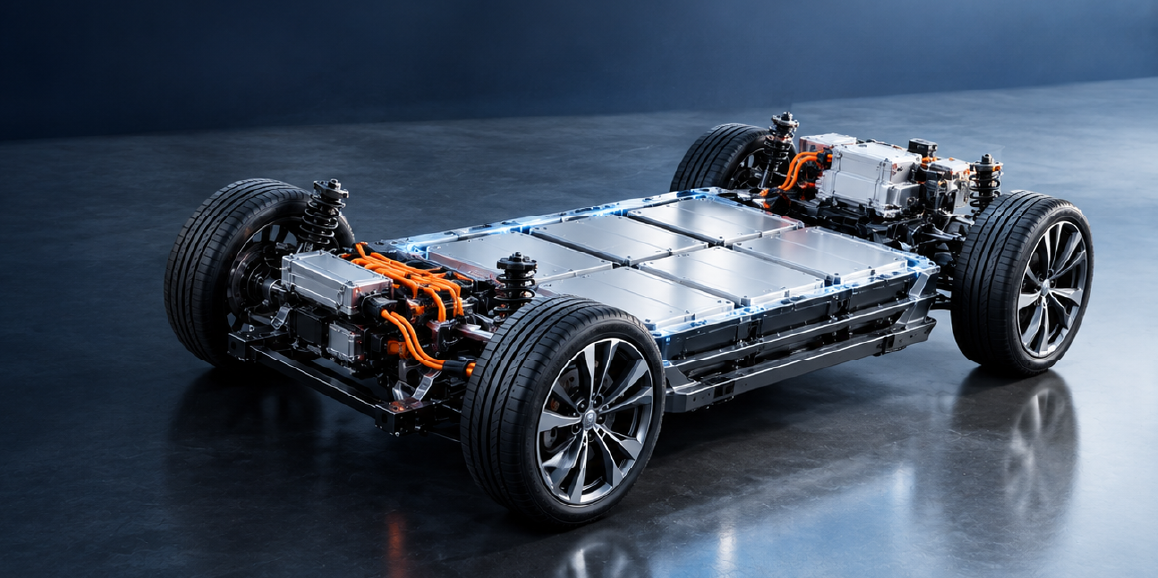
Read the CADFEM guide to smart BMS functions, automotive thermal management, centralized vs. modular architectures, and Ansys simulation
Read Article →
How to set up, execute and analyze a laminated composite impact simulation using native layered shell sections in Ansys Workbench LS-DYNA.
Laminated composite materials such as fiber reinforced polymers (FRPs) offer exceptional strength-to-weight ratios, making them essential in aerospace, defense, and automotive engineering. However, predicting their behavior under low velocity drop test or high velocity ballistic impact is complex due to coupled failure mechanisms like matrix cracking, fiber breakage, and inter-laminar delamination.
Integrating Ansys Composite PrepPost (ACP) with the LS-DYNA explicit solver inside Ansys Workbench provides a robust framework to tackle these challenges. While ACP is a powerful preprocessor, many users prefer defining composite laminates directly through layered shell sections in Workbench LS-DYNA. A Layered Section is used to define composite materials or structures made up of multiple layers, each with its own material properties, thickness, and orientation.
This blog outlines how to set up, execute, and analyze a laminated composite impact simulation effectively.
Simulating layered composites requires tracking precise fiber orientations, stacking sequences, and thickness variations.
MAT_054 (MAT_ENHANCED_COMPOSITE_DAMAGE) or MAT_058 (MAT_LAMINATED_COMPOSITE_FABRIC). These models evaluate failure criteria (Chang-Chang or Hashin) for individual plies.When configuring a multi-layer composite section directly in LS-DYNA via Workbench, integration rules and element formulations must be defined carefully.
ELFORM=2 (default Belytschko-Tsay) or ELFORM=16 (fully integrated shell), which prevent hourglassing and handle membrane warping effectively.Single Shell Limitation: Standard layered shell sections excel at capturing in-plane progressive damage. However, because a single multi-layer shell element assumes perfect bonding between plies through its integration points, capturing out-of-plane interlaminar delamination requires dedicated tiebreak interfaces or cohesive zone elements, which fall outside a pure single-shell setup.
Typical Workbench workflow:
Engineering Data → Geometry → Model → Layered section definition → Mesh → LS-DYNA Setup (Initial Velocity, Contact, Boundary conditions) → Solve → Post-processing (Workbench or LS-PrePost)
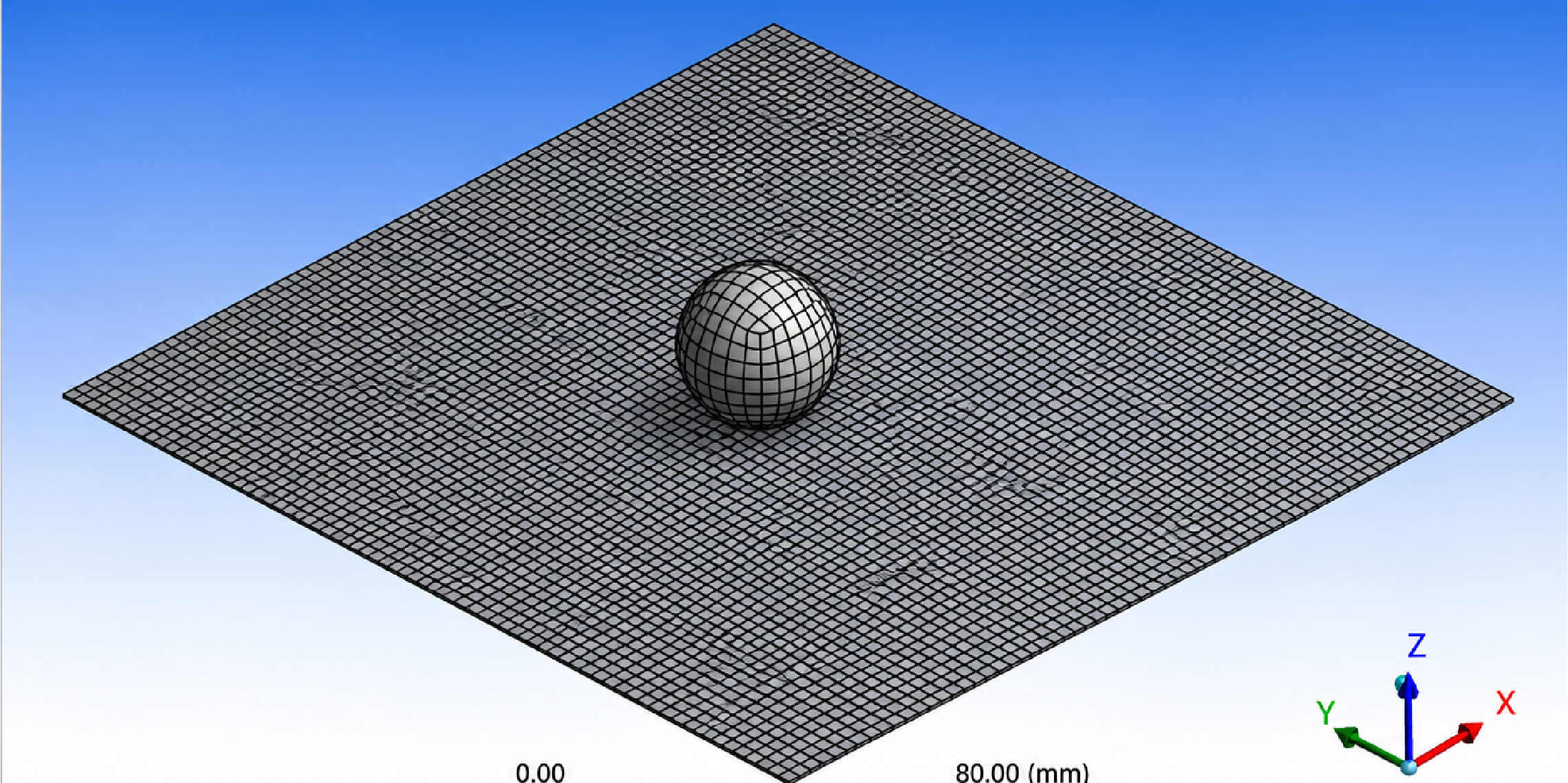
A 24 mm spherical impactor at 30 m/s impacts a 2.5 mm thick laminate plate with dimensions 150 × 180 mm. The analysis aims to capture the dynamic response and damage evolution of the plate. The laminate is modeled as a five-layer structure with the cross-ply stacking sequence [0/90/0/90/0].
Impactor Material: Default Structural Steel was considered for the spherical impactor.
| Structural Steel Properties | |||
|---|---|---|---|
| Symbol | Description | Value | Unit |
| ρ | Density | 7850 | kg m−3 |
| E | Young's Modulus | 200 × 103 | MPa |
| ν | Poisson's Ratio | 0.3 | — |
Composite Material: Sourced from the Engineering Materials library as Epoxy Carbon UD (230 GPa) Prepreg, governed by *MAT_054.
| Epoxy Carbon UD (230 GPa) Prepreg with *MAT_054 Properties | |||
|---|---|---|---|
| Symbol | Description | Value | Unit |
| ρ | Density | 1490 | kg m−3 |
| Ea | Longitudinal Elastic Modulus | 1.21 × 10⁵ | MPa |
| Eb | Transverse Elastic Modulus | 8600 | MPa |
| Gab | In-Plane Shear Modulus | 4700 | MPa |
| Xt | Longitudinal Tensile Strength | 2231 | MPa |
| Xc | Longitudinal Compressive Strength | 1082 | MPa |
| Yt | Transverse Tensile Strength | 29 | MPa |
| Yc | Transverse Compressive Strength | 100 | MPa |
| Sc | In-Plane Shear Strength | 60 | MPa |
Failure Criteria & Parameters: To accurately capture progressive damage and element failure, specific directional failure strain (DFAIL*) parameters were integrated, and the Tsai-Wu criterion was selected for matrix failure.
| Epoxy Carbon UD (230 GPa) Prepreg with *MAT_054 Failure Data | |||
|---|---|---|---|
| Parameter | Description | Value | Unit |
| DFAILT | Max Strain for Fiber Tension (Xt/Ea) | 0.01844 | mm/mm |
| DFAILC | Max Strain for Fiber Compression (−Xc/Ea) | −0.00894 | mm/mm |
| DFAILM | Max Strain for Matrix Failure (Yt/Eb) | 0.00337 | mm/mm |
| DFAILS | Max In-Plane Shear Strain (Sc/Gab) | 0.01277 | mm/mm |
Layup Definition: The layered section layup was defined after scoping directly to the laminate geometry in Workbench.
Discretization & Contact: A 2 mm global mesh was utilized, resulting in linear hexahedral elements for the impactor and quadrilateral shell elements for the laminate. A frictional contact interaction was defined with the laminate acting as the slave surface, the rigid impactor as the master surface, and a friction coefficient of 0.2.
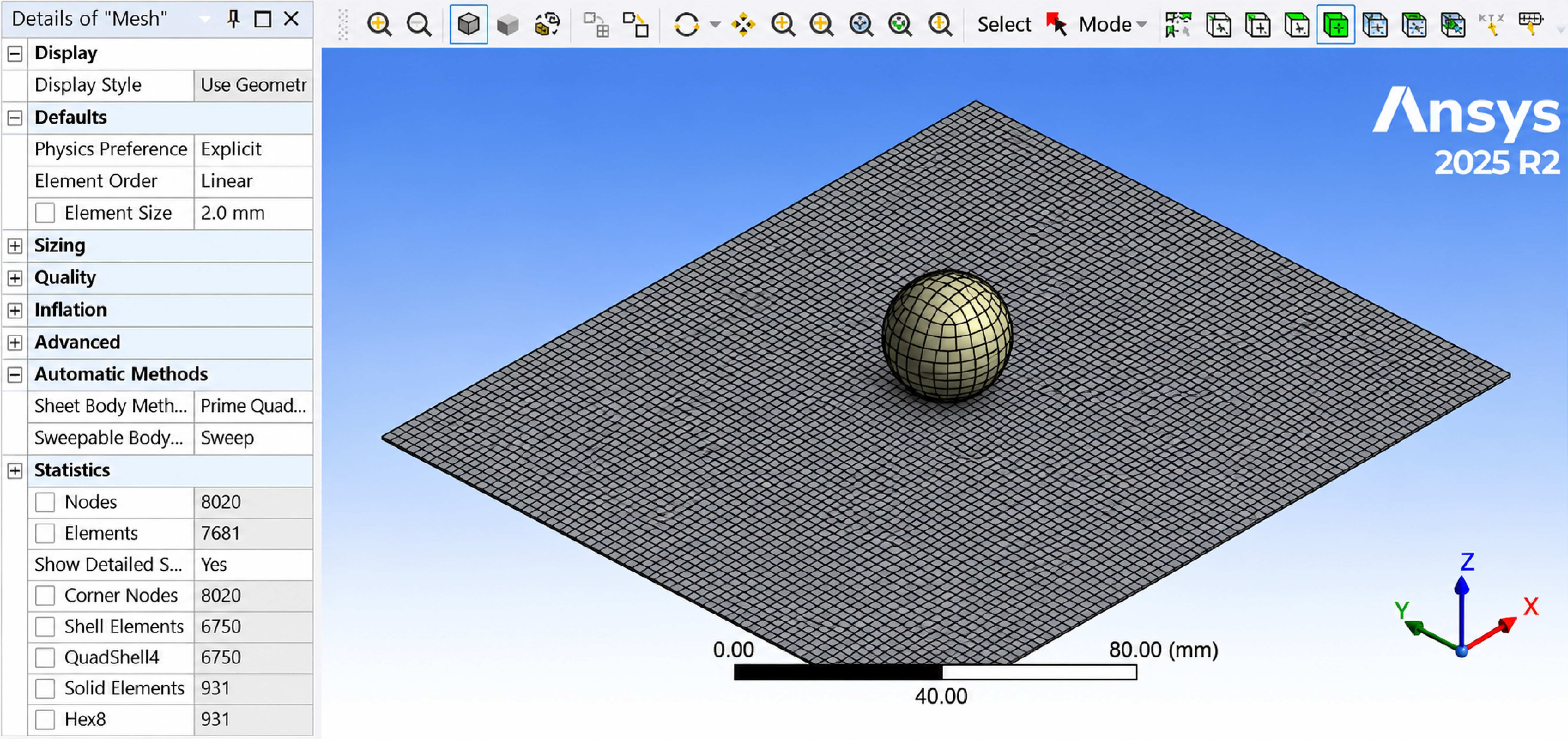
Composite Representation: It is set to Part so that the PART_COMPOSITE family of keywords will be created, which is a simpler setup for shells.
Impact Conditions & Constraints: The spherical impactor is given an initial velocity of 30 m/s, striking the center of the composite laminate plate that is held completely fixed at the edges.
Simulation Duration: An explicit transient end time of 3 ms was selected to fully capture the impact, deflection, and damage propagation event.
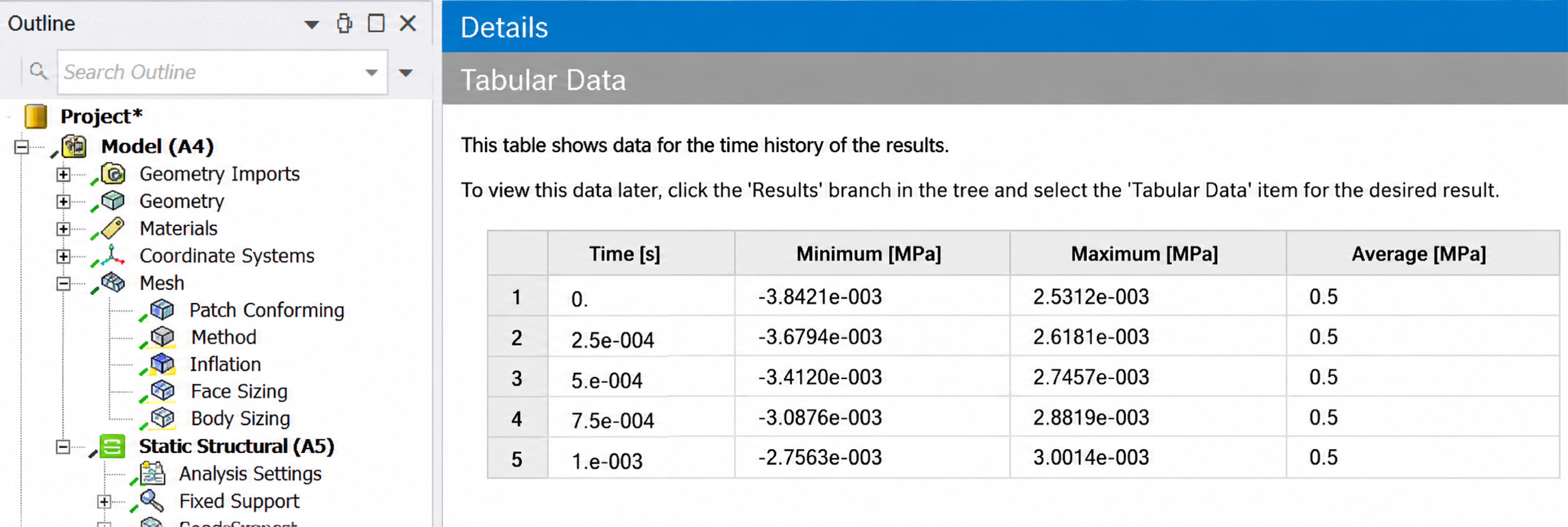
When the impactor strikes, the clamped plate first bends smoothly to absorb the energy. As the force builds up, the material reaches its strength limits (governed by the Tsai-Wu criterion), leading to matrix cracking and progressive element tearing at the centre of the impact site.
Utilizing native layered sections in Workbench LS-DYNA provides a fast, transparent, and script-friendly alternative to heavy preprocessors. By managing ply angles, material definitions, and failure criteria directly at the section level, engineers can achieve highly accurate impact and perforation simulations with complete control over the solver deck.
 Multi Physics
Read the CADFEM guide to smart BMS functions, automotive thermal management, centralized vs. modular architectures, and Ansys simulation
Read Article → Structures
Di tengah pesatnya perkembangan teknologi rekayasa, adopsi CAE di Indonesia menjadi kunci utama dalam meningkatkan efisiensi dan produktivitas berbagai sektor industri.
Read Article → Electronics
Learn how to use Ansys HFSS SBR+ for 77 GHz automotive radar simulation, evaluating radome effects, antenna performance, radiation patterns, and installation.
Read Article →Connect with CADFEM experts for advanced simulation, automation, and engineering solutions tailored to your industry.