What Is a Battery Management System? Guide for Automotive Applications
Read the CADFEM guide to smart BMS functions, automotive thermal management, centralized vs. modular architectures, and Ansys simulation
Read Article →
Explore what coma aberration is, why it degrades off-axis image quality, and how Ansys Zemax OpticStudio enables engineers to quantify, visualize, and correct coma — reducing costly physical iterations.
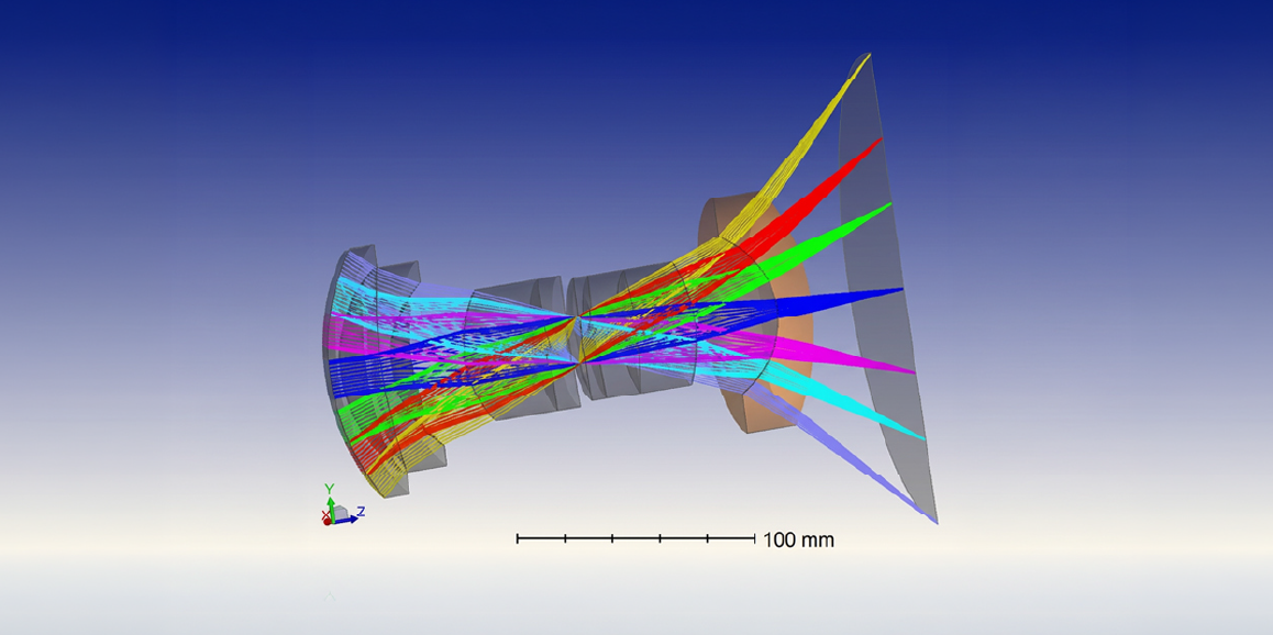
In real optical systems, image quality is often limited not by diffraction alone but by optical aberrations arising from lens geometry, alignment, and field dependence.
Among third-order Seidel aberrations, coma aberration plays a crucial role in degrading off-axis image quality, producing comet-shaped blur patterns that are especially noticeable in imaging, astronomy, and automotive vision systems.
Modern optical design tools such as Ansys Zemax OpticStudio allow engineers to quantify, visualize, and correct coma efficiently during the design stage — reducing costly physical iterations.
This blog explains:
Coma is an aberration affecting off-axis object points, where rays passing through different zones of a lens fail to converge at a single image point.
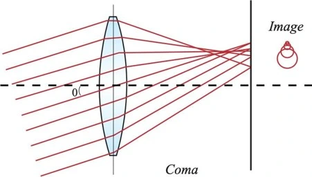
Instead of a sharp spot, the image appears:
This distortion reduces spatial resolution, contrast, and measurement accuracy in imaging systems.
Coma arises primarily due to:
Mathematically, coma is a third-order aberration proportional to h · y², where:
Thus, coma increases rapidly for wide-angle optics.
One of the strongest advantages of Zemax is its ability to directly visualize aberrations through multiple analysis tools.
In Zemax:
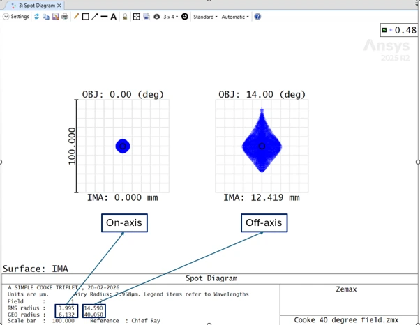
This provides immediate confirmation of coma presence.
The tangential and sagittal ray fans in Zemax reveal:
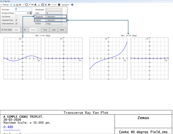
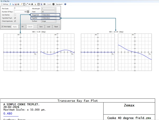
This helps designers identify which surface contributes most.
Zemax expresses coma via Zernike polynomial coefficients:
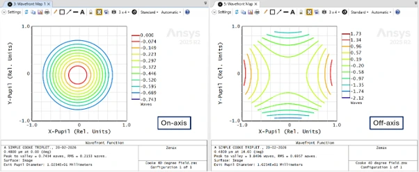
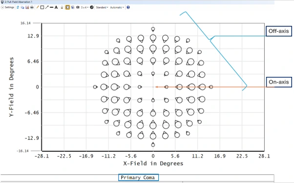
Monitoring these values during optimization enables quantitative coma reduction.
Stars near the edge of the field appear stretched into comets, reducing observation clarity.
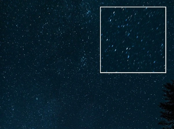
Edge-field blur degrades:
Measurement errors increase due to asymmetric point spread.
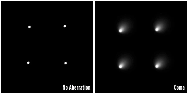
Hence, coma control is critical in wide-field imaging design.
Zemax allows rapid evaluation of:
Proper stop placement can significantly suppress coma.
Refer below example wherein a plano convex lens's performance is evaluated with aperture stop being on left side of the lens & with aperture stop being on right side:
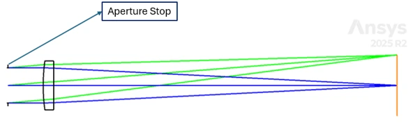
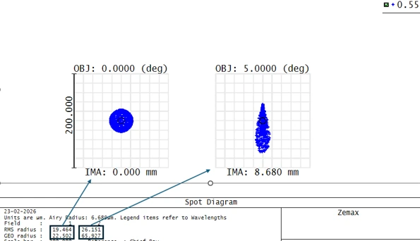
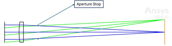
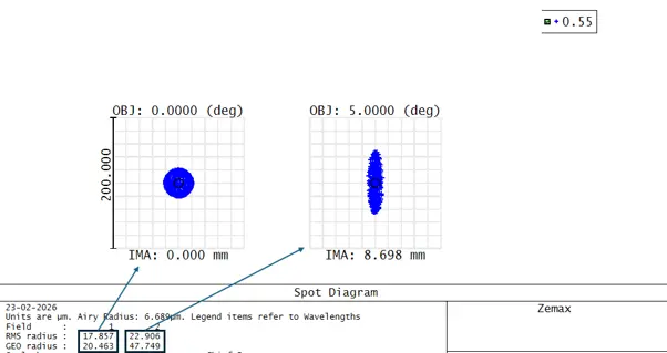
Observe the geo radius values for off-axis field spot, you can see that spot size as well as coma spread is less when the aperture stop is placed appropriately, for the above case stop on right side of lens works fine.
Using Zemax optimization:
Refer below example wherein one air-spaced doublet or 2 singlets are modelled & optimized, both the optical systems have same aperture size, focal length & lens material, but both are exhibiting different performances as per lens bending achieved through optimization iterations.
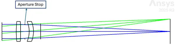
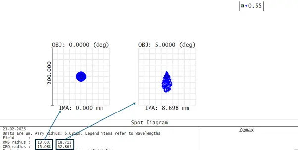
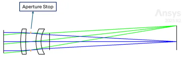
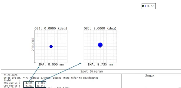
Observe the geo radius values for off-axis field spot, you can see that spot size as well as coma spread is less of OS 2 optical system compared to OS 1 despite having the same configurations & start design, OS 2's lens curvatures were optimized a bit more.
This is one of the most effective classical corrections.
Doublets or symmetric lens groups in Zemax:
Refer below example:
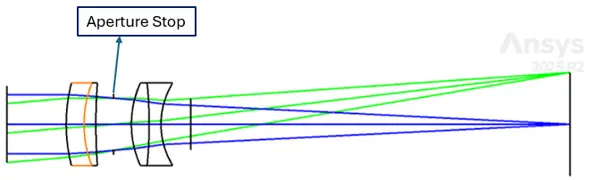
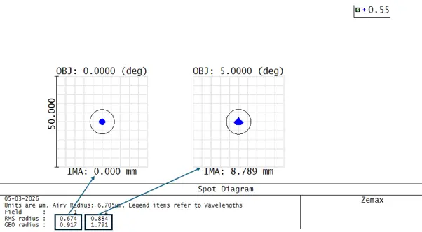
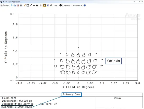
Compared to OS 2 system, OS 3 system is way better performing in terms of spot & coma spread. Also, the primary coma aberration (in waves) is quiet a low value. This tells us that a doublet lens pair is far superior to a singlet lens pair for coma correction.
Zemax makes it straightforward to:
This is widely used in modern camera optics.
Refer the below example:
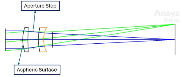
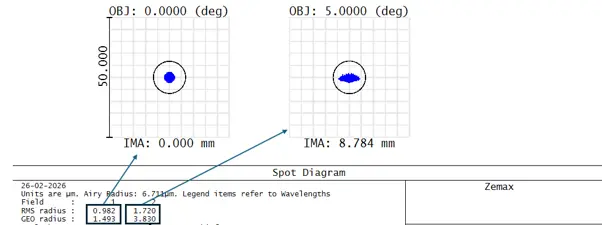
OS 2 & OS 4 are same configuration optical system, but OS 4's performance in terms spot & coma spread is far less than the OS 2's performance.
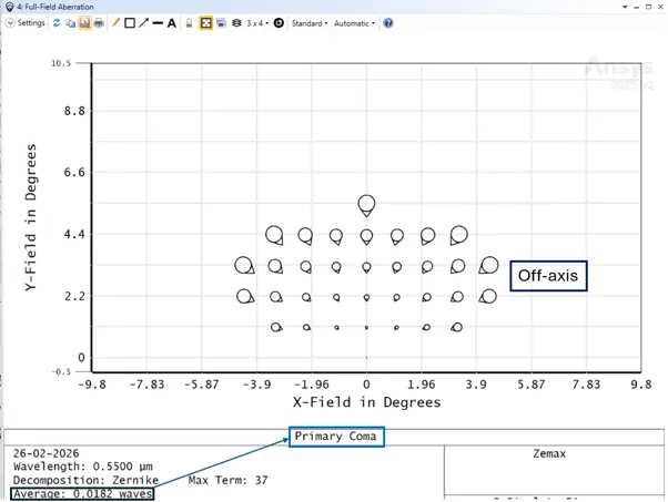
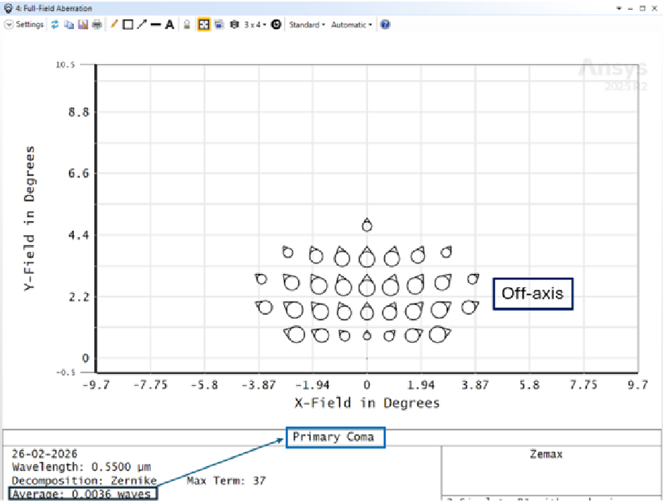
Further if we look at the primary coma using full field aberration plot, it indicates that OS 4 system has less coma aberration (in waves) compared to OS 2
Without simulation, coma correction requires trial-and-error prototyping.
Zemax enables:
This dramatically reduces design cycle time and development cost.
Coma aberration is one of the most important factors affecting off-axis image quality in wide-field optical systems. Its presence can significantly degrade resolution and introduce distortions that impact applications ranging from astronomy to machine vision and automotive sensing.
Through advanced optical design software such as Ansys Zemax OpticStudio, engineers can perform detailed optical aberration analysis, identify the sources of coma, and implement systematic coma aberration correction strategies.
Mastering these techniques allows optical designers to achieve high image quality across the entire field of view while reducing development time and minimizing the need for physical prototyping.
 Multi Physics
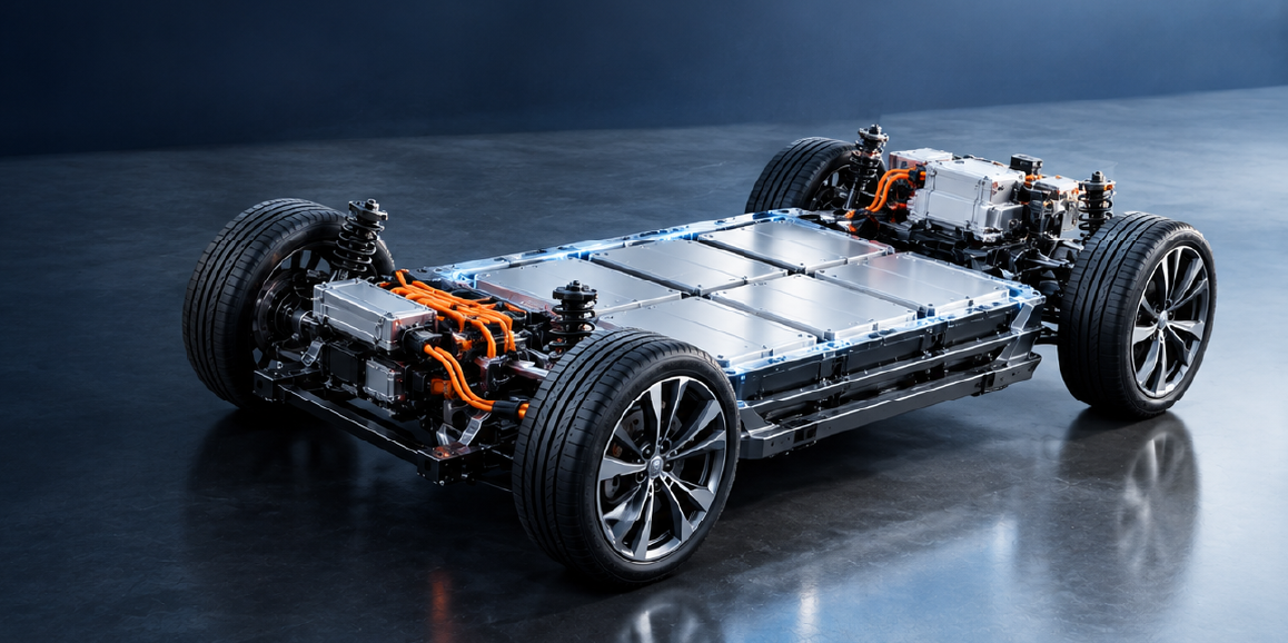
Read the CADFEM guide to smart BMS functions, automotive thermal management, centralized vs. modular architectures, and Ansys simulation
Read Article → Structures
Di tengah pesatnya perkembangan teknologi rekayasa, adopsi CAE di Indonesia menjadi kunci utama dalam meningkatkan efisiensi dan produktivitas berbagai sektor industri.
Read Article → Electronics
Learn how to use Ansys HFSS SBR+ for 77 GHz automotive radar simulation, evaluating radome effects, antenna performance, radiation patterns, and installation.
Read Article →Connect with CADFEM experts for advanced simulation, automation, and engineering solutions tailored to your industry.