What Is a Battery Management System? Guide for Automotive Applications
Read the CADFEM guide to smart BMS functions, automotive thermal management, centralized vs. modular architectures, and Ansys simulation
Read Article →
Dive deep into fluid–structure interaction, blade shape morphing, aeroacoustics, and PyFluent automation — completing the digital design workflow for ceiling fans beyond basic airflow prediction.
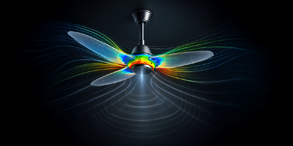
In Part 1 of this blog series, we explored how simulation using Ansys Fluent enables accurate airflow prediction and IS 374-compliant performance assessment for ceiling fans — helping engineers optimise designs for better energy efficiency and air delivery without costly physical prototyping.
In Part 2 below, we dive deeper into fluid–structure interactions, blade optimization, acoustics, and simulation automation to complete the digital design workflow.
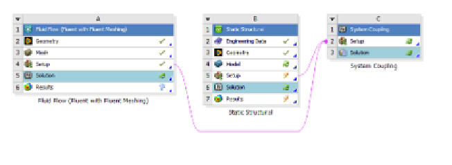
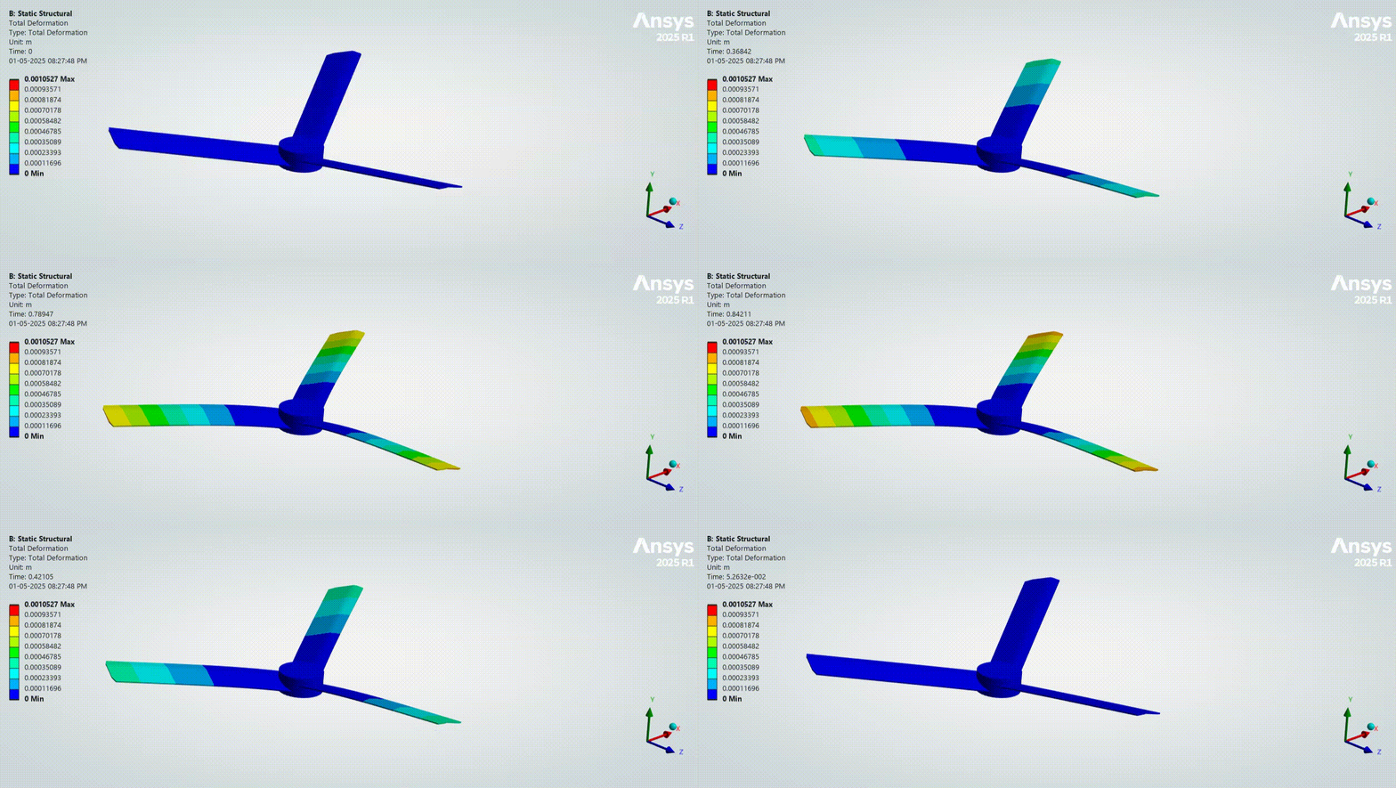
During operation, ceiling fan blades are not only subjected to aerodynamic loads but also to self-weight and centrifugal forces. If blade design lacks structural capacity, these loads can cause undesired deformation or failure. Under fluid loading, blades deform — changing their shape and, consequently, the airflow patterns they generate. This creates a coupled behaviour where the modified flow affects further blade deformation, making it critical to capture these interactions early in the design cycle.
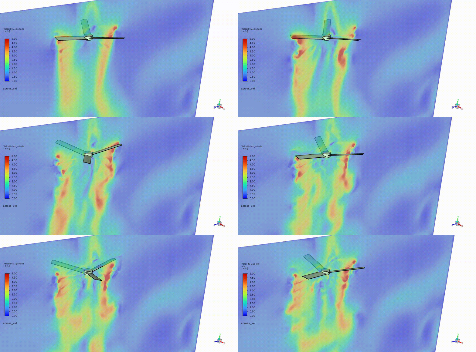
Designers seek blade profiles that maximise airflow and efficiency while maintaining structural integrity. Traditional parametric optimisation (e.g., DOE with Ansys optiSLang) can require significant computational resources. Gradient-based methods offer a more targeted path.
A gradient-based solver, typically using an adjoint method, computes the sensitivity of performance metrics (such as torque or drag) relative to geometric changes. This identifies the regions of the blade most sensitive to performance objectives — such as reducing torque or improving downward flow. Once sensitivity regions are known, shape morphing modifies the mesh locally to explore improved geometries.
The process iteratively:
This method often reveals design improvements that traditional parameter sweeps might miss.

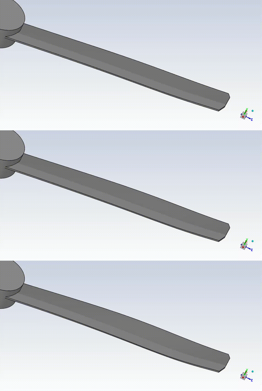
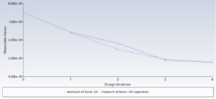
In addition to gradient-based methods, multi-objective parametric optimization (e.g., with Ansys optiSLang) enables systematic exploration of geometric variations against performance goals. These studies can reveal trade-offs between torque, air delivery, and structural constraints to guide robust blade designs.
Acoustics has become a key differentiator in modern consumer appliances. Ceiling fans are used for long durations, and prolonged exposure to unwanted noise can be uncomfortable for users.
From a physics perspective, noise is an acoustic pressure wave that propagates through air and is perceived by the human ear. Fan noise can originate from multiple sources, including air cutting by blades, vibration of fan components, and electric motor excitation. Noise generated due to airflow is referred to as airborne noise, while vibration-induced noise is known as structure-borne noise.
Blade profile and shape have a significant influence on airborne noise, whereas assembly quality and component fitment largely affect structure-borne noise. In some cases, fluid-induced pressure fluctuations excite structural vibrations, which then radiate as acoustic waves.
Conducting experimental acoustics studies can be time-consuming and expensive due to multiple test iterations and physical prototyping. Simulation provides an efficient alternative by offering early-stage insights into acoustic performance.
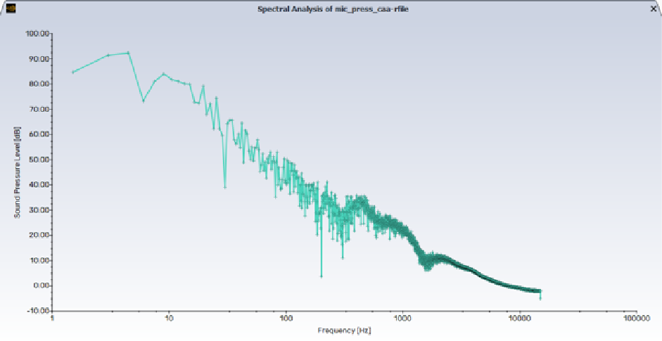
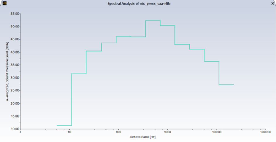
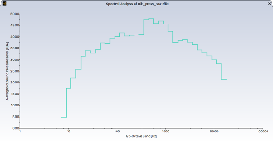
Within CFD simulations, pressure monitors record time-dependent pressure fluctuations. These signals can be post-processed using Fast Fourier Transformation (FFT) to analyze noise levels across frequencies. To capture very small pressure variations—down to 2 × 10⁻⁵ Pa—scale-resolving turbulence models are required. Although computationally intensive, the use of GPU-accelerated Ansys Fluent solvers significantly reduces turnaround time.
A steady-state simulation is typically performed first to establish a converged flow field, which then serves as the starting point for scale-resolving simulations.
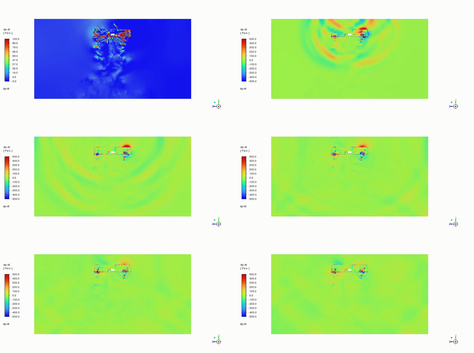
Several methodologies are available for sound propagation analysis, each offering a different balance between accuracy and computational cost. Computational Aeroacoustics (CAA) resolves sound propagation directly by solving the Navier–Stokes equations, providing high fidelity but requiring substantial computational resources. Integral methods, such as the Ffowcs-Williams and Hawkings (FWH) model, reduce computational cost by solving wave equations for sound propagation, making them suitable for far-field noise prediction. Coupled approaches use dedicated acoustic solvers with CFD-derived source data, while broadband noise models offer fast, steady-state-based directional noise estimates.
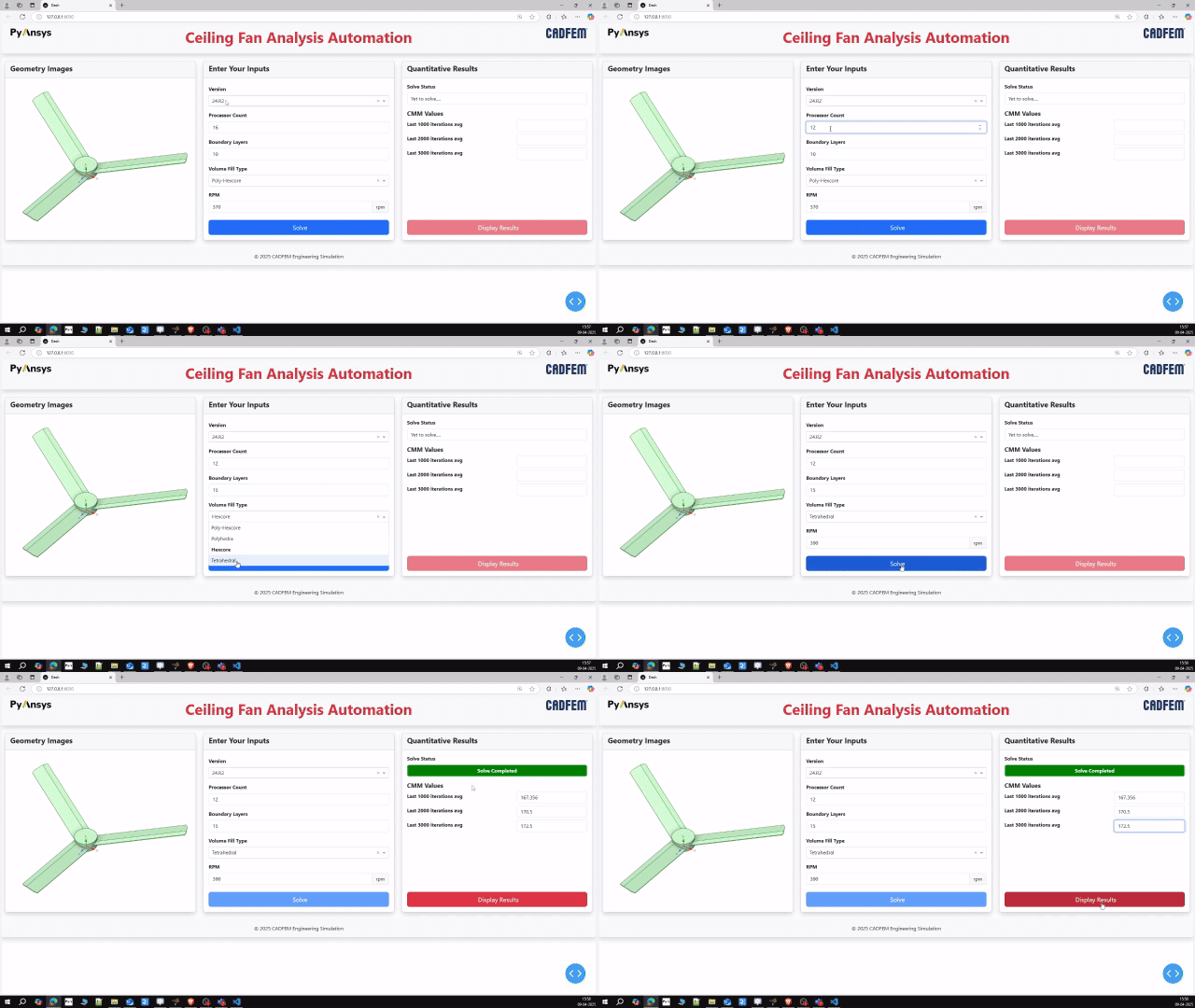
As simulation workflows grow more complex, automation becomes essential for productivity. IS 374 air delivery testing must be conducted for multiple blade designs, making manual setup repetitive and time-consuming.
Using PyFluent, the entire IS 374 simulation workflow can be automated — from model setup and execution to post-processing — ensuring consistency while significantly reducing overall analysis time. This approach is particularly valuable when evaluating design variants, where the same boundary conditions and solver settings must be applied repeatedly with precision.
Designing an efficient and reliable ceiling fan requires more than optimizing airflow alone. By integrating fluid–structure interaction, blade optimization, aeroacoustics, and simulation automation, engineers can realistically evaluate blade deformation, improve performance, reduce noise, and accelerate design validation. Together with the aerodynamic insights from Part 1, these advanced Ansys simulation techniques enable a holistic, physics-based approach to ceiling fan design, supporting better engineering decisions with reduced reliance on physical prototyping.
 Multi Physics
Read the CADFEM guide to smart BMS functions, automotive thermal management, centralized vs. modular architectures, and Ansys simulation
Read Article → Structures
Di tengah pesatnya perkembangan teknologi rekayasa, adopsi CAE di Indonesia menjadi kunci utama dalam meningkatkan efisiensi dan produktivitas berbagai sektor industri.
Read Article → Electronics
Learn how to use Ansys HFSS SBR+ for 77 GHz automotive radar simulation, evaluating radome effects, antenna performance, radiation patterns, and installation.
Read Article →Connect with CADFEM experts for advanced simulation, automation, and engineering solutions tailored to your industry.