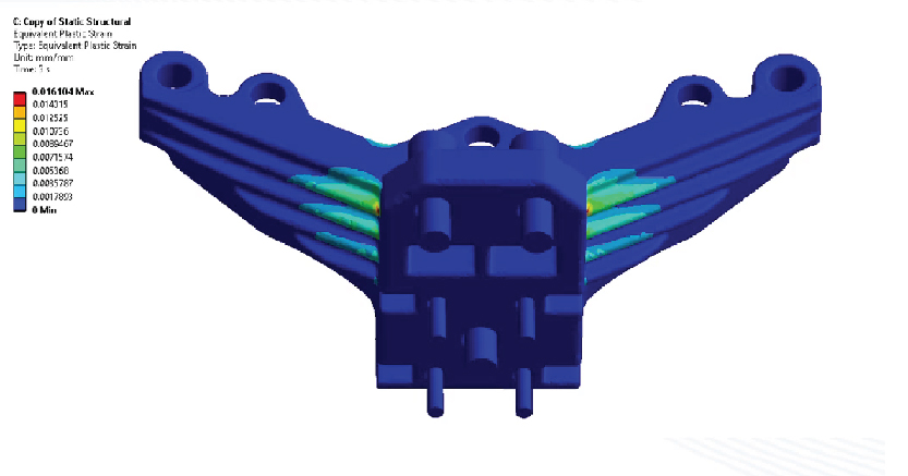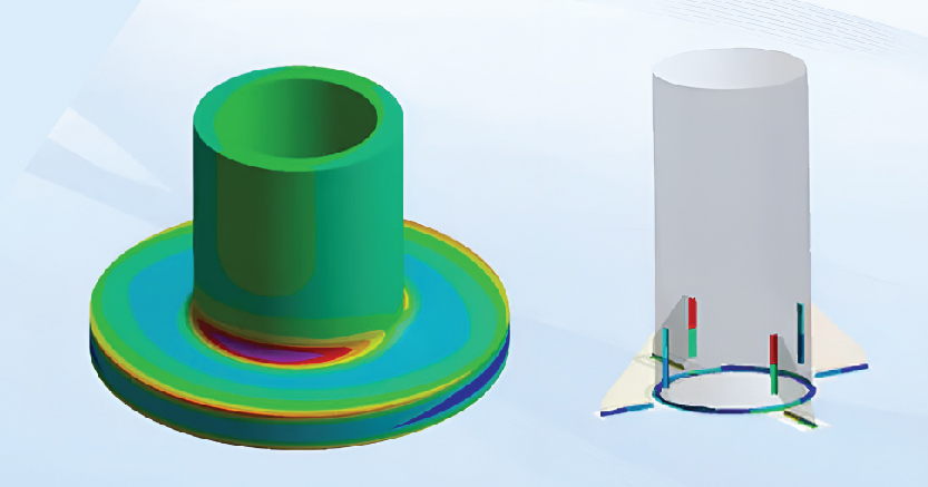
Fast strength evaluation with guideline-compliant verification according to the FKM standard. Full-surface strength verification of non-welded volume components according to FKM in compliance with guidelines. Strength verification of welds on shell and volume structures according to FKM in compliance with guidelines.
Identification of critical load cases through basic load case combinations involves analyzing different loading scenarios by combining simple individual load cases to determine the most critical conditions. This approach helps in identifying the worst-case load combinations that result in maximum stress or deformation, enabling engineers to focus on the most demanding operational conditions for design optimization and safety assessment.
Full-surface strength verification according to FKM (Forschungskuratorium Maschinenbau) guidelines involves evaluating complex, user-defined solid components to ensure they meet established fatigue and static strength requirements. This method assesses all surface areas under various loading conditions, checking for compliance with FKM’s fatigue criteria, such as stress endurance limits, material properties, and loading cycles. The verification process includes detailed stress analysis, often using finite element simulation, to capture stress concentrations and load distributions across the entire component. By applying FKM criteria, engineers ensure that components meet rigorous standards for safety and durability, especially in high-stress or cyclically loaded environments. This is crucial for achieving reliable performance over a component’s intended lifespan.
The reduction of time for strength evaluations to a minimum, even for complex scenarios, involves optimizing simulation processes and leveraging advanced computational techniques. This can be achieved by using efficient meshing strategies, parallel processing, and automation tools to streamline the analysis of stress, fatigue, and deformation. Simplified yet accurate models, along with pre-defined material and load conditions, further expedite evaluations, allowing for faster results without compromising accuracy. These methods enable quicker decision-making in design and improve overall efficiency, particularly in scenarios involving complex geometries or multi-load conditions.
Relief of the user from manual inputs or error-prone formulas involves automating the data entry and calculation processes within simulations. By integrating predefined parameters, material databases, and standardized formulas, the system reduces the need for users to manually input values or derive complex equations. This automation minimizes human error, ensures consistency, and accelerates the simulation workflow. It also allows engineers to focus on higher-level decision-making and analysis, improving efficiency and reliability in design and evaluation tasks.
Fields of application for welded structures, castings, and milled structures involve a wide range of industries where components undergo complex loading and require high strength and durability. Welded structures are commonly used in construction, automotive, and aerospace, where joint integrity and fatigue resistance are critical. Castings are essential in manufacturing components with complex shapes, such as engine blocks or pump housings, where material properties and stress distribution are key factors. Milled structures are used in precision engineering and machining, where accurate tolerances and surface finishes are necessary for high-performance applications. Simulation and strength evaluation in these areas ensure that these components can withstand operational stresses and meet safety and performance standards.

